


Honeywell Pilot Gateway
New Website Brings Free Tech Pubs and 24/7 Support Directly to Pilots
By Chris Van Cise
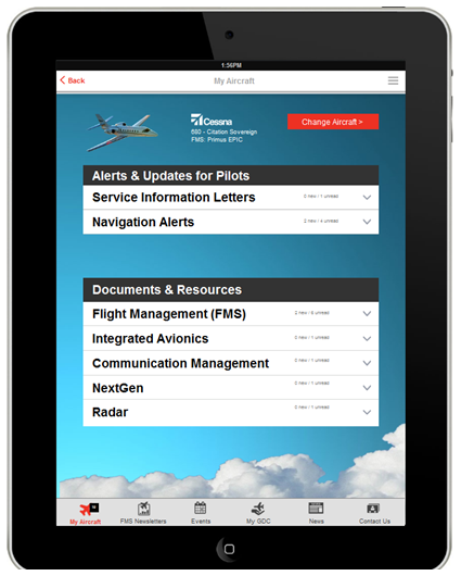
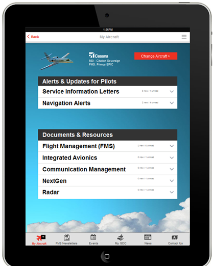
Honeywell's new website for pilots has arrived. Accessing key resources and support is now faster and easier than ever. The Pilot Gateway is designed to work on computers, tablets, and smart phones. A dedicated iPhone® and iPad® app is coming soon.
The Pilot Gateway provides users with free access to many of Honeywell's business and general aviation technical publications, videos, and other resources tailored to pilots, and allows them to easily ask operational questions and provide feedback. The goal is to give Honeywell customers "one stop shopping" in an easy to use interface.
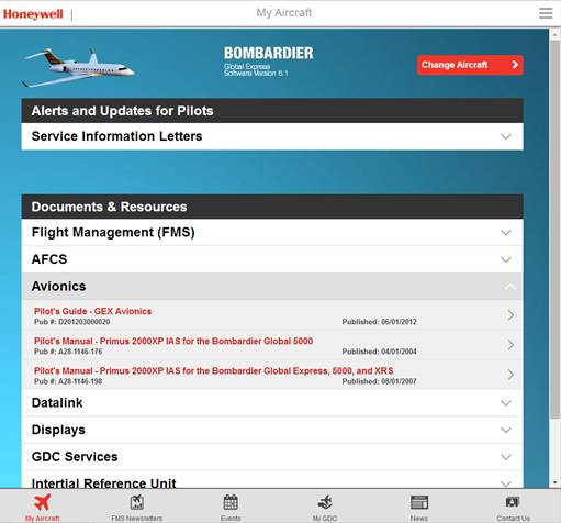 |
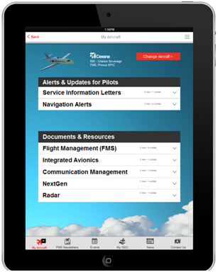
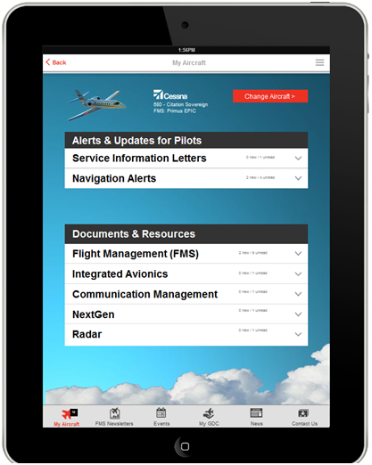
| Honeywell Pilot Gateway "My Aircraft" Page |
Additional features, including access to this newsletter, product and industry updates, and an events calendar will be added soon. Once the iPad® and iPhone® app is released, users will be able to receive push notifications and enjoy additional offline functionality.
Pilot-Designed
The Pilot Gateway is a powerful tool for flight crews who use Honeywell products and services. In order to make sure users can fully enjoy all of its benefits the first time they log in, the website and app have been designed to be as simple and intuitive as possible. New users will be familiar with the interface right away.
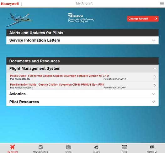 |
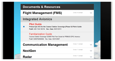
| Example: FMS Resources for the Cessna Citation Sovereign Phase 5.2 |
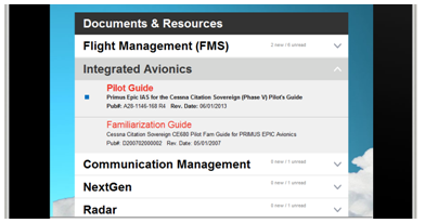
Careful resource organization is a key part of Pilot Gateway's simplicity. The design team, including members of Honeywell's Global Customer Committee (GCC), decided to organize resources by aircraft type and system. For example, to access the Integrated Avionics System Pilot's Guide, the user simply selects Avionics, and then selects the Pilot's Guide from the menu. A detailed description appears and allows the pilot to view it, save it, or share it.
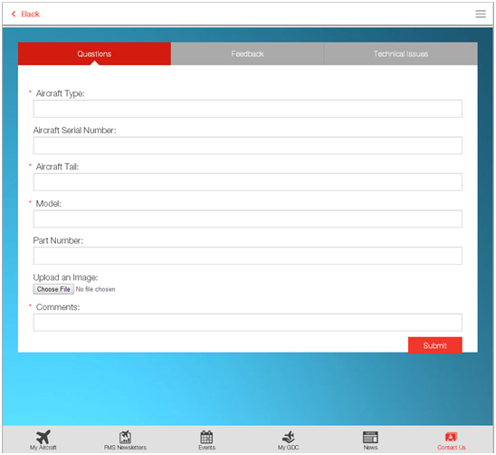
Communicating with Honeywell through the Pilot Gateway is just as simple. From the "Contact Us" page, users are greeted with three tabs: Questions, Feedback, and Technical Issues. Each tab contains a short form with the ability to upload photos and write detailed comments. Questions, feedback, and technical issues are sent directly to the correct Honeywell team, and responses and updates are provided via email.
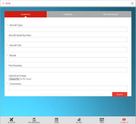 |
| Simple Forms Guide Pilots through Submitting Questions, Feedback, and Technical Issues |
The Honeywell Pilots App is one of many great ideas that have originated from the GCC. For more information on joining or making contributions to the committee, please visit here.
Honeywell Pilot Gateway
Register or Login.
Training Specialist Chris Van Cise supports the Global Data Center, data link, and technical publications for Honeywell Flight Technical Services. He can be reached at Christopher.VanCise@Honeywell.com
The Radar Corner
The RDR-4000 3D Volumetric Radar – The Beginning
By Stephen D. Hammack
When Honeywell started development of the RDR-4000 radar system, they conducted a study to understand more about how pilots use, and misuse radar. The study looked at several factors, including:
- Training and understanding of current radar systems
- Weather detection and avoidance of conventional radar vs. RDR-4000
- Usability, acceptability and workload of new RDR-4000 modes
- How to enhance weather awareness
- How to improve crew decision-making
- How to maintain flight crew workload at an acceptable level
- How to simplify flight crew training
The HF study included 46 pilots from France, UK, USA, Norway, Japan, Taiwan, Canada and the Philippines. Honeywell was looking for the "typical line pilot," but ended up with a sample that had a mean age of 52, and a mean experience level of 12,533 hours. The study consisted of a short questionnaire (8 Questions) followed by a short briefing on the RDR-4000. The pilots were then put in a task simulator to evaluate situational awareness and decision making.
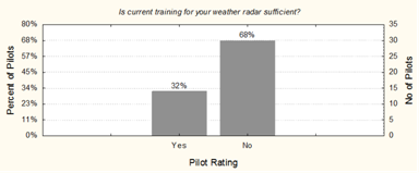
- "What training?"
- "Mostly taught by on-the-job training, so myths and wrong concepts are easily passed on."
- "We learn by using weather radar out in the real world. Training is practically non-existent."
This article will look at the eight questions test subjects were asked. Readers can keep track of their own answers and compare them to the test group's responses. The first four answers will be discussed this month, and the final four answers will be discussed in the September issue of Direct-TO.
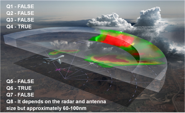
Q1 - In level flight with the antenna tilt set to zero degrees, the radar will show me everything at my flight level – True or False
Q2 - At cruise level with the aircraft nose up 2 degrees, I should set tilt two-degrees down to compensate for the nose-up attitude – True or False
Q3 - Objects that pose a threat can be positively identified by adjusting the tilt so the bottom of the beam is parallel to the ground (with an 18 inch antenna) plus 2.8 degrees – True or False
Q4 - The antenna tilt should be set to compensate for the effects of the Earth's curvature – True or False
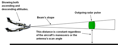
Q5 - For radars with an 18 inch antenna, the beam is 5.6 degrees wide, and the radar will show targets at their true color level as long as part of the target is inside the beam – True or False
Q6 - At cruise altitudes greater than FL 310, radar targets displayed as green at short range should be avoided – True or False
Q7 - If I am climbing (or descending) at a three-degree flight path angle, I should set my tilt angle to 3 degrees to see weather along my flight path – True or False
Q8 - With the weather radar you are currently using, do you know the range at which it is no longer calibrated and returns are not displayed at their true color levels? If yes, what is the range? – Yes or No, and if Yes what range?

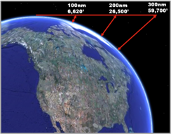
Humans learned a long time ago that the earth isn't flat. Unfortunately, many pilots seem to forget that fact when setting tilt. If a laser pointer was placed on a perfectly flat table and a measurement of how far the earth fell off at different distances was taken, it would look like the picture to the left. Close to the aircraft it's not that bad, 6,620 feet at 100nm. However, at 200nm it is over 26,000 feet, and at 300nm it is almost 60,000 feet.
It's clear from the picture why question 1 is false. If tilt is set at zero, or near zero, storm cells could fall under the beam at longer ranges. Obviously if setting tilt at zero isn't safe, then setting tilt to plus 2.8 degrees uptilt wouldn't be safe either, so question 3 is also false. There is another reason why tilt shoud never be set to zero, or near zero at high cruise altitudes. Radar is designed to reflect off of water droplets. When setting the tilt to look straight ahead, the beam would intersect cells at high altitude where only frozen ice crystals exist, and those cannot be seen by radar.
This is one of the main reasons the "Cruise Ground Park" technique is reccomended for setting tilt at cruise altitudes. The beam should be lowered until ground returns appear at the outer edge of the display. The benefit of this is that the cell will walk though the beam making it easy to detect, and if ground returns can be seen behind the cell, then radar attenuation and shadowing are not an issue. There's also no need to worry about antenna size, beamwidth, or the earth's curvature effect.

Question two was testing understanding of antenna stabilization and how it relates to tilt management. If antenna stabilization is on and working, the antenna is always referenced "to the horizon". If zero degrees of tilt is set, it doesn't matter if the aircraft is three degrees pitch up, three degrees pitch down, or in a roll. The antenna will scan zero degrees relative to the horizon. If antenna stabilization is turned off or stops working, then the antenna is referenced to the longitudinal axis of the aircraft. In this case if the aircraft is two degrees pitch up and the crew wants to scan zero degrees relative to the horizon, they would need to tilt two degrees down.
Check back next month for a look at the answers to the last four questions in the test.
Program Pilot Stephen Hammack supports Honeywell Apex and radar for Flight Technical Services. He can be reached at Stephen.Hammack@Honeywell.com
Mandates Corner
Getting Approved for ADS-B – A Follow Up
By Jim Johnson
The December issue of Direct-TO featured an article outlining when Letter of Authorization (LOA) / Operations Specification (Ops Spec) A353, approval for ADS-B Out, was required for operators and what information the operator was required to provide when applying. Initially, the FAA's approval process required a significant amount of internal coordination, resulting in long timelines to get the LOA / Ops Spec. The FAA has since announced a policy change that will expedite the signoff process. The following outlines some of the changes to the process. The term LOA (14 CFR Part 91 operators) will be used throughout this article interchangeably with Ops Spec (14 CFR Part 135 operators).
Reason for the Change
The original ADS-B LOA was written to meet the approval requirements of Transport Canada and Nav Canada. They have recently rescinded requirements for ADS-B airspace, and no longer require a paper approval. They are moving to a system used by several other countries - if they see the aircraft is transmitting the correct ADS-B signal they will grant access to the airspace. As a result, the FAA now has the ability to modify the LOA requirements to become less burdensome.
ADS-B LOA / Ops Spec Number Change
One of changes entails the LOA / Ops Spec number changing from A353 to A153. This may seem trivial, however, understanding that a "3XX" series LOA / Ops Spec is considered a "non-standard" approval and therefore must be reviewed, coordinated, and approved at multiple levels of the FAA. When A153 is available, review and approval will be done solely at the FSDO level.
Required Documentation for A153 Application
Operators must submit the following documentation when requesting LOA A153. The A153 Application Checklist, which will be issued concurrently with the new LOA, will have all the requirements for an LOA application. The completed checklist will be required along with the supporting documentation.
- Letter of Request
- Airplane Flight Manual (AFM), Airplane Flight Manual Supplement (AFMS), Flight Operations Manual (FOM), or Pilot's Operating Handbook (POH), or equivalent indicating the airplane's ADS-B system complies with either 14 CFR § 91.227, AC 20-165, or EASA AMC 20-24.
- Make, model, and part number of the ADS-B transmitter and positioning source installed on each airplane.
- A copy of Ops Spec B050 annotating where A153 will be used (not required for Part 91 operators)
- Part 91 operators will need to provide a statement indicating that their pilots have knowledge of current air traffic ADS-B directives for the intended areas of en route operations and will comply with § 91.703
Before submitting an application for ADS-B Out, operators are encouraged to review AC 90-114A. This advisory circular provides excellent background on the requirements and use of ADS-B as well as references to international requirements.
Operators That Already Have A353
Operators that currently have LOA A353 are NOT required to replace it with A153. However, an existing A353 may be replaced with A153 if requested by the operator without further documentation. If an operator has submitted an application and is awaiting approval, the approval will be issued in A153. In the future, A353 will be used for approval of ADS-B In applications.
Helpful Links
A153 Checklist
FAA Notice 8900.296
Senior Training Specialist Jim Johnson supports Honeywell Go Direct™ and regulatory issues for the Flight Technical Services team. He can be reached at James.Johnson2@Honeywell.com
Engine Insights
ITT Exceedance During Engine Start
By Helmuth Eggeling
As with all turbine engines, exceeding engine limitations, especially during engine starts, may result in an accelerated wear, damage or failure of the Low Pressure/High Pressure (LP/HP) compressors, the Low Pressure Turbine/High Pressure Turbine (LPT/HPT) sections, and/or the reduction gearboxes or accessory gearboxes. The most common limitations are generally listed as turbine temperature limits (ITT or EGT) and rotational speed limits (N1 and N2).
Turbine engine limitations are typically classified as either Type 1 or Type 2 events:
The type 1 classification represents a notice indicating an engine parameter is approaching a Type 2 exceedance. In short, Type 1 notices are used to anticipate a potential maintenance action.
A type 2 occurrence is automatically recorded. The ECU automatically records the peak temperature and the time that the turbine temperature is above the threshold.
The most critical engine limitation, however, is the temperature of the gas flow as it enters the HPT section at Airflow Station 4 (see Figure 1).
AIRFLOW STATIONS
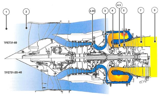
Figure 1
As a quick review, the following table defines each Airflow Station as illustrated in Figure 1:
| Station Number | Description |
| 1 | Station 1 parameters are used on test cell runs and are taken at the inlet screen. |
| 2 | Just forward of the fan. At this station, the Pt2/Tt2 probe is installed to sample the engine inlet air pressure and temperature. |
| 2.45 | Discharge pressure from the LP compressor. Can be used during test cell or performance run to determine the health of the LP compressor. |
| 3 | Discharge pressure from the HP compressor. It is used by the Fuel Control Unit (FCU) and the surge-bleed-valve (SBV) system. |
| 4 | Location of the HPT nozzles. |
| 4.5 | Location of the Interstage Turbine Temperature (ITT) probes for general temperature references. |
| 5 | Location of the first stage LPT nozzle assembly. |
| 7 and 9 | Exhaust airflow stations. The pressures from these stations provide engine pressure ratios that are used to determine and validate thrust. |
Published engine operating limitations in the Airplane Flight Manual (AFM) are FAA approved and require specific operator and/or maintenance action if any limits have been exceeded. Normally the Electronic Control Unit (ECU) monitors the turbine temperature and limits fuel flow when a rapid rise of ITT is detected in order to avoid a hot start.
As a rule-of-thumb, a potential hot start is imminent or should be anticipated when:
- RPM (N2) acceleration is less than normal. Consistently timing every engine start will reveal a step change. For example:
- N2 should reach 10% within 6 seconds from starter engagement.
- ITT should increase within 10 seconds after the power lever has been advanced to idle.
- ITT rises rapidly toward maximum start limit (red line).
In the rare event that the ITT limiting feature is malfunctioning, it is incumbent upon the pilot/operator to abort the engine start manually and in accordance with FAA approved AFM procedures. It must be stressed here, indicated ITT will continue to rise slightly (even after the fuel has been cut off during an aborted engine start), reach a peak temperature and then drop. Therefore, abort the engine start about 50°C before the maximum ITT redline to prevent a temperature exceedance [Note: This is not a limitation, only a guideline. Always observe the rate of ITT rise, which could give a clue of whether the limit will be reached or exceeded.].
If, however, an exceedance occurs during an engine start, it is important to observe and log the peak temperature and the duration above maximum start temperature (as published in the AFM). That information aids maintenance technicians in determining the action required to correct the discrepancy that caused the exceedance. Without that information, the technician has to take the conservative path, which means complying with the most stringent guidelines documented in the Light Maintenance Manual (LMM). Typically this means removing the engine in order to perform a Hot Section Inspection (HSI).
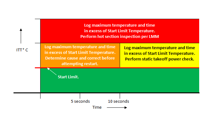
Figure 2
Generic Example of Actions Required if Starting ITT Limit is Exceeded
Carefully monitoring the turbine temperature during an engine start, judging the rate at which the temperature increases and making an early decision to abort an engine start normally precludes an exceedance of the maximum start limit. If, however, an exceedance during an engine start occurs, logging the peak temperature and the duration above maximum start temperature can make a huge difference in time and money required to return the aircraft back into service.
Helmuth Eggeling is a Honeywell Lead Test Pilot and Pilot Advisor. He can be reached at Helmuth.Eggeling@Honeywell.com or +1 (602) 231-2697 for questions on the above subject and other Honeywell engine topics.
Tools of the Trade
Inmarst Launches Jet ConneX, Honeywell Master Distributor
| Passengers aboard business aircraft can soon access internet, boasting the same speeds they're used to at home and in the office. Jet ConneX (JX), the business aviation service powered by Inmarsat's Global Xpress network, is set to debut in the first half of 2015. It will deliver passengers and operators fast, global in-flight Wi-Fi across land and sea. As the exclusive provider of hardware for JX, Honeywell offers JetWave, a line of cabin connectivity systems. JetWave is capable of delivering downlink speeds of up to 33 mbps for business aircraft, allowing passengers to video conference, send and receive large files, and stream high quality television and movies while airborne. This high-performance SATCOM system turns the cabin into a serious mobile office. |
 |
Even as consumer technologies continue to evolve, JetWave will provide a strong connectivity backbone, allowing aircraft to stay on the cutting edge for many years to come. JX provides four times the bandwidth compared to current systems that rely on the Ku-band network.
As operators invest in their cabins, installing high-performance SATCOM systems and providing reliable internet access to passengers remain on top of the list of must-haves. Working alongside major data provider partners including SATCOM1 and Aircell, Inmarsat's JX and Honeywell's JetWave bring new possibilities to business aviation.
To request more information, please email FTS@Honeywell.com.
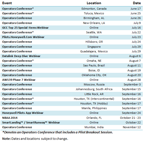
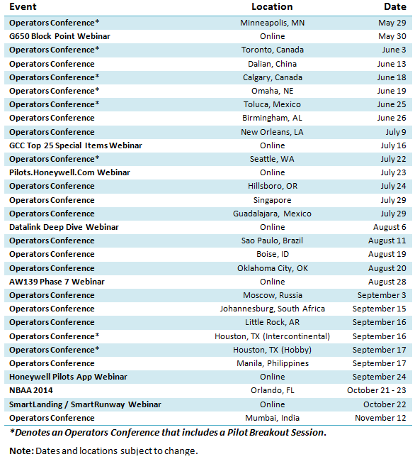
Events and Training Calendar
2014 Events and Training
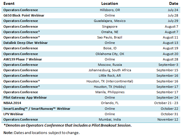
Honeywell's Flight Technical Services team travels extensively to bring pilots the latest information on regulations, new technology, and Honeywell product updates. Through Pilot Breakout Sessions at Honeywell Operators Conferences, one-on-one training, entry into service support, and live webinars, Honeywell pilots are on a mission to keep operators informed.
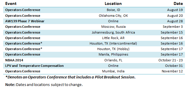 |
Most of this year's Operators Conferences include pilot breakout sessions with time for participants to ask questions and connect one-on-one with program pilots. Primary topics will include Mandates and Honeywell Solutions, Future Concepts, Service Information Letters, Global Customer Committee Project Overview, and a Pilots.Honeywell.Com Beta-Test Evaluation and Feedback Session. As always, all operator conferences are completely free. Please email FTS@Honeywell.com for more information.
Honeywell Pilot Gateway
New Website Brings Free Tech Pubs and 24/7 Support Directly to Pilots
By Chris Van Cise
Honeywell's new website for pilots has arrived. Accessing key resources and support is now faster and easier than ever. The Pilot Gateway is designed to work on computers, tablets, and smart phones. An iPhone® and iPad® app will debut in September.
The Pilot Gateway provides users with free access to many of Honeywell's business and general aviation technical publications, videos, and other resources tailored to pilots, and allows them to easily ask operational questions and provide feedback. The goal is to give Honeywell customers "one stop shopping" in an easy to use interface.
 |
| Honeywell Pilots App "My Aircraft" Page |
Additional features, including access to this newsletter, product and industry updates, and an events calendar will be added in August. Once the iPad® and iPhone® app is released in September, users can receive push notifications and enjoy additional offline functionality.
Pilot-Designed
The Pilot Gateway is a powerful tool for flight crews who use Honeywell products and services. In order to make sure users can fully enjoy all of its benefits the first time they log in, the website and app have been designed to be as simple and intuitive as possible. New users will be familiar with the interface right away.
 |
| Example: Integrated Avionics System Resources for the Cessna Citation Sovereign |
Careful resource organization is a key part of Pilot Gateway's simplicity. The design team, including members of Honeywell's Global Customer Committee (GCC), decided to organize resources by aircraft type and system. For example, to access the Integrated Avionics System Pilot's Guide, the user simply selects Integrated Avionics, then selects the Pilot's Guide from the menu. A detailed description appears and allows the pilot to view it, save it, or share it.
Communicating with Honeywell through the Pilot Gateway is just as simple. From the "Contact Us" page, users are greeted with three tabs: Questions, Feedback, and Technical Issues. Each tab contains a short form with the ability to upload photos and write as much as they like. Questions, feedback, and technical issues are sent directly to the correct Honeywell team, and responses and updates are provided via email.
 |
| Simple Forms Guide Pilots through Submitting Questions, Feedback, and Technical Issues |
The Honeywell Pilots App is one of many great ideas that have originated from the GCC. For more information on joining or making contributions to the committee, please visit here.
Honeywell Pilot Gateway
Register or Login.
Training Specialist Chris Van Cise supports the Global Data Center, data link, and technical publications for Honeywell Flight Technical Services. He can be reached at Christopher.VanCise@Honeywell.com
Mandates Corner
FANS 1/A with NZ FMS
By Jim Johnson
With the mandates for FANS data link in the North Atlantic on the horizon, many operators of NZ FMS are now thinking about equipping. Questions about what equipment and upgrades are required for FANS capability are coming in every day. The following provides an overview of what changes will be required.
Cockpit Voice Recorder
In the US, the FAA mandated that aircraft that have data link equipment installed after 2010 (Part 135) and 2012 (Part 91) provided capability to record data link messages. Hence, operators will be required to install a cockpit voice recorder with data link recording capability (CVR-D).
VHF Data link (VDL) Radio and Satcom
FANS utilizes a combination of VHF and satcom for communication. A VHF Data link Radio (VDR) is required for FANS. A VDL Mode 2 radio is not required for FANS but will support future growth to meet the European requirement for PM-CPDLC. satcom is required for FANS data link and must be certified to DO-178B software level D. This is true whether an operator uses Inmarsat or Iridium.
FMS Software and Control Display Unit (CDU)
NZ FMS operators will require FMS upgrade 6.1 as well as a FANS Activation software load. This upgrade incorporated FANS functionality which includes the standard ATC message sets used in data link communications. Additionally, an update to the CD-810 or upgrade to CD-820 is required to include changes necessary for accessing ATC data link pages within the FMS. The CD-820 is on a strict allocation and may not be available in many instances. Honeywell is introducing the CD-830 in mid 2015 as a replacement to the CD-820. The CD-810 is compatible with FANS but requires accessing the NAV Index page to gain access to the ATC page.
Communication Management Unit (CMU)
Operators will be required to replace the existing AFIS Data Management Unit with a Communication Management Unit (CMU). The CMU provides message routing functionality as well as flight deck alerting that is required for ATC data link. The Mark III CMU will be the short term solution for FANS 1/A+. For PM-CPDLC, most aircraft have a lifetime exemption. However, Honeywell is evaluating new products to meet this need as demand arises.
Need to Equip?
The mandate for FANS data link in the North Atlantic has begun and is being implemented in phases. By 2020 the entire NAT region will require FANS data link above FL290.
For more information about the required equipment and upgrades for a particular aircraft, please contact Honeywell Flight Technical Services at FTS@honeywell.com.
To learn more about mandates, go to http://aerospace.honeywell.com/mandates
Senior Training Specialist Jim Johnson supports Honeywell Go Direct™ and regulatory issues for the Flight Technical Services team. He can be reached at James.Johnson2@Honeywell.com
Tools of the Trade
How SmartRunway™/SmartLanding™ Improves Safety
By Thea Feyereisen
On the night of December 22, 2009, a Boeing 737-800 departed Miami for Kingston, Jamaica, carrying 148 passengers and six crew members. After a reportedly bumpy and turbulent flight, the airplane landed too long on the runway, crashed through an airport perimeter fence and traveled across a road. The aircraft broke into three major pieces, causing injuries, and came to halt on some sand dunes just above the Caribbean Sea. Information obtained from the flight data recorder indicates that the aircraft touched down more than 4000 feet down the 8900 foot runway. Despite the focus on aircraft accidents in the news, it is important to remember that flying is still safer than almost any other type of travel. The excellent safety record of air travel is due in part to the aviation safety community that studies the statistics and trends of aircraft accidents and incidents and identifies areas for improvement. |
 |
| New technology is introduced (and sometimes mandated) to mitigate high frequency categories of accidents. Two examples of this are Enhanced Ground Proximity Warning System and Traffic Alert and Collision Avoidance System. | |
Despite the focus on aircraft accidents in the news, it is important to remember that flying is still safer than almost any other type of travel. The excellent safety record of air travel is due in part to the aviation safety community that studies the statistics and trends of aircraft accidents and incidents and identifies areas for improvement. New technology is introduced (and sometimes mandated) to mitigate high frequency categories of accidents. Two examples of this are Enhanced Ground Proximity Warning System and Traffic Alert and Collision Avoidance System.
The top two causes of fatalities in commercial aviation are loss of control in-flight and controlled flight into terrain. Recently, I blogged about an invention, Synthetic Vision Systems, that provides counter measures to both of those categories of accidents. This time, I'm going to talk about an invention that can reduce the risk of occurrence for the third most frequent cause of fatalities in aircraft accidents (but most frequent non-fatal type accident): runway excursion.
Runway Excursion
Since 1990, runway safety has appeared almost every year on the National Transportation Safety Board "Most Wanted" list. Runway excursion is the most frequent type of landing accident. The most common type of a runway excursion is a runway roll off-- where the aircraft roll out extends beyond the end of the runway. Excursions may occur during landing, takeoff or taxi.
Significant factors that lead to runway excursions include:
- Unstabilized Approach (too fast , too high)
- Landing Long
SmartRunway and SmartLanding
Honeywell's safety group investigated the top causal factors of runway excursions that cost the industry $1 billion dollars annually for injuries, damage, repairs and inspections. A new safety product family called SmartRunway (SR) and SmartLanding (SL) was developed and introduced as a result. SR/SL is an easy software enhancement upgrade available to the Enhanced Ground Proximity Warning System (EGPWS) that is standard equipment on many aircraft. It provides timely aural and visual warnings during taxi, takeoff and landing that increase situational awareness reducing the risk of runway excursions which account for more than 95% of total runway related accidents.
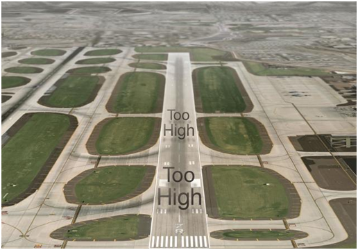 |
SR/SL provides positional advisories and graphical alerts to crew members to reduce the likelihood of a runway excursion or runway confusion. SR/SL alerts use aircraft data, including GPS, for position, speed and flight path. This is compared to a worldwide airport runway database already stored on the aircraft. Example alerts provided by SR/SL include if the aircraft is "Too High!" or "Too Fast!", or not configured properly, "Flaps!" In addition, it provides alerts at critical points to prevent runway confusion, such as "Approaching Runway 07 Right" and alerts pilots if they attempt to takeoff from a taxiway instead of a runway, "On Taxiway!" The SR/SL system also provides distance remaining advisories, e.g., "2000 Feet Remaining", to enhance crew awareness of aircraft along-track position relative to the runway end.
Smart Runway and Smart Landing are a significant safety enhancement that helps break the chain of events that lead to runway accidents. Although not mandated, a runway awareness advisory system is one of the safety enhancements identified by the Commercial Aviation Safety Team that can help further reduce the accident rate. Both SmartRunway and SmartLanding are available for commercial and business aviation platforms currently equipped with Honeywell's EGPWS. The easy to install SR/SL EGPWS software feature will reduce runway excursion and other runway safety risks and provide a safety net to protect passengers, crew and aircraft.
Thea Feyereisen is an Engineering Fellow in the Flight Safety Systems group of Honeywell's Aerospace Advanced Technology organization. Her blog can be found here.
Global Data Center Update
Creating Trip Kits
By Kirk Waterhouse
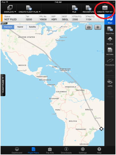
Subscribers to the Global Data Center have access to the MYGDC iPad app. The app is an invaluable tool for preflight planning and in-flight flight plan viewing. By setting up a "Trip Kit" a pilot has their flight plans and weather packages anywhere they need them, without printing a single sheet of paper. Once a trip kit is created, the flight plans, text weather, and charts are accessible on the iPad without an internet connection. They can also be emailed or printed if desired.
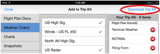
To get started setting up a trip kit, either create a flight plan, or select Flight Plans. Next, select Create Trip Kit.
 |
This screen allows users to add additional items for offline viewing. Tap the items desired. Once added, they appear in the list on the right side of the screen. The weather used will include the most current reports at the time of creating the Trip Kit. A standard set of items can be configured under the "Settings" tab.
Charts such as SID's, STAR's, Approach charts, and Airport Diagrams may be added:
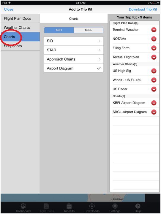 |
If the snapshot button ( ) has been tapped on the flight plan screen, these items can be added to the trip kit for future viewing.
When finish adding items, tap the "Download Trip Kit" button.
 |
Tap the Trip Kits button on the bottom row. This will bring up a list of all trip kits that have been created recently:
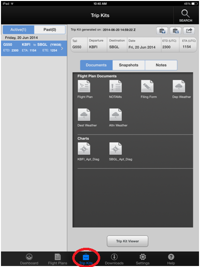 |
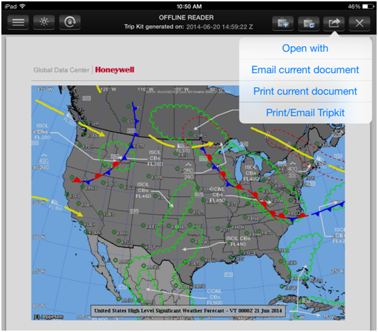
Tapping on any of the items in the trip kit will bring up the Trip Kit Viewer, which has a side bar on the left of the items in the trip kit. To hide the sidebar, tap on the document displayed. To bring the sidebar back, tap on the  button.
To print or email the trip kit tap the  button (printing requires a wireless printer with "Airprint" functionality, that is connected to the same WiFi network).
 |
Have questions about this topic, International Trip Services, the Global Data Center, or datalink in general? Please contact FTS@Honeywell.com.
Flight Technical Services Q&A
FMS 100 Waypoint Limitation
By David Rogers
The Honeywell legacy Flight Management Systems (NZ and EPIC series) are limited to 100 waypoints in an active flight plan. This was done in accordance with the original requirements of various OEMs and satisfied the vast majority of operations at the time. However, as procedures have become more complex, resulting in lengthier flight plans, the likelihood of exceeding the maximum number of waypoints has increased. This is especially true during international flights. When the waypoint limit is reached, manual loading/entering is required, which requires increased focus from the flight crew to avoid gross navigational errors.
When the maximum number of waypoints is reached, the FMS Scratchpad message "FLIGHT PLAN FULL" is displayed. Subsequently, additional SIDs, STARs, airways, and waypoints cannot be added to the flightplan until prior waypoints are sequenced-out. The remaining waypoints then need to be entered manually by the pilot.
This issue was recently brought up through Honeywell's Global Customer Committee (GCC). Flight Technical Services was asked to investigate and explore possible solutions. It was determined that the issue has been addressed in the NG-FMS product line. The maximum number of waypoints was increased in NG-FMS to approximately 200, depending on the OEM. The issue will begin to be resolved as future platforms migrate to NG-FMS, however crews must continue to be vigilant to the issue, and when necessary, carefully enter and crosscheck all manual entries.
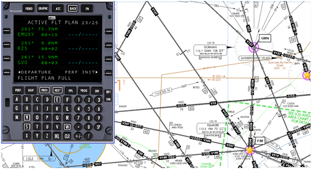 |
| "FLIGHT PLAN FULL" Scratch Pad Message |
David Rogers is the Honeywell Program Pilot for Gulfstream and Cessna aircraft. He can be reached via email at David.Rogers@Honeywell.com.
Engine Insights
Available Now - Win 7 E-Engine Interface Software
| New Windows 7-compatible software is available now for the Electronic Engine Interface (EEI) tool for both the AS907 and TFE731 families of Honeywell propulsion engines. Users can download the Version 3.00.00 software at the MyAerosopace.com portal by clicking on the "Software & Data" tab and selecting "Engine & APU Software Downloads." The Windows 7 version also is available on CD. The portal also contains links to the EEI FAQ document and Windows 7 training material. This FAA-qualified EEI tool lets business aircraft operators download engine condition and fault data directly from engine control units to a laptop computer, which enables maintenance crews to monitor engine performance and perform condition-based maintenance. Previously, the EEI software (Version 2.09.00) ran exclusively on the Windows XP operating system. Now it's available for either Windows XP or Windows 7. The addition of a Windows 7 version was increasingly important as Microsoft stopped supporting Windows XP, and Windows 7 has become a preferred operating system for personal computers. Version 3.00.00 is available in both Enterprise 32-bit & Professional 64-bit versions. |
 |
Developing a Windows 7 version of the software was one of the top five action items identified by the Honeywell Global Customer Committee (GCC), an advisory board comprised of pilots and maintenance chiefs from leading business aircraft operators from around the world. Honeywell is also developing Windows 7-compatibility for a variety of other software tools to better serve customers.
At the same time, Honeywell has made improvements to the software to address problems with previous versions and add enhancements. As a result, the new software is easier and more intuitive for users.
For more information or to order the EEI kit or software, visit the MyAerosopace.com portal; contact Honeywell Aerospace Technical Support (ATS) at aerotechsupport@honeywell.com or by calling 855-808-6500 in the U.S. or Canada, or 602-365-6500 elsewhere.
Events and Training Calendar
2014 Events and Training
Honeywell's Flight Technical Services team travels extensively to bring pilots the latest information on regulations, new technology, and Honeywell product updates. Through Pilot Breakout Sessions at Honeywell Operators Conferences, one-on-one training, entry into service support, and live webinars, Honeywell pilots are on a mission to keep operators informed.
 |
Most of this year's Operators Conferences include pilot breakout sessions with time for participants to ask questions and connect one-on-one with program pilots. Primary topics will include Mandates and Honeywell Solutions, Future Concepts, Service Information Letters, Global Customer Committee Project Overview, and a Pilots.Honeywell.Com Beta-Test Evaluation and Feedback Session. As always, all operator conferences are completely free. Please email FTS@Honeywell.com for more information.
Honeywell Pilots App
Website Launches Next Month
By Chris Van Cise
Honeywell's new website for pilots is in the final stages of development and testing. Arriving next month, it is designed to work on desktop computers, laptops, tablets, and smartphones. An iPhone® and iPad® app will follow in September.
The Honeywell Pilots Website and App will provide users with free access to many of Honeywell's business and general aviation technical publications, videos, and other resources, and allow them to easily ask operational questions and provide feedback. The goal is to give Honeywell customers "one stop shopping" in an easy to use interface.
 |
| Honeywell Pilots App "My Aircraft" Page |
Additional features, including access to this newsletter, product and industry updates, and an events calendar will be added in August. Once the iPad® and iPhone® app is released in September, users can receive push notifications and enjoy additional offline functionality.
Pilot-Designed
The website and app will be powerful tools for flight crews who use Honeywell products and services. In order to make sure users can fully enjoy all of its benefits on release, the website and app have been designed to be as intuitive as possible. New users will be familiar with the interface moments after logging in.
 |
| Integrated Avionics System Resources for the Cessna Citation Sovereign |
The design team, including members of Honeywell's Global Customer Committee (GCC), suggested organizing resources by aircraft type and system. For example, to access the Integrated Avionics System Pilot's Guide, the user simply touches Integrated Avionics, and selects the Pilot's Guide from the menu. A detailed description appears and allows the pilot to view it, save it, or share it.
 |
 |
| Pilot Resources Organized by Aircraft System | Question and Feedback Submission Page |
Pilots can be sure they are ready to enjoy the website and app as soon as they are launched by signing up to receive Honeywell Aerospace news and updates here.
The Honeywell Pilots App is one of many great ideas that have originated from the GCC. For more information on joining or making contributions to the committee, please visit here.
Training Specialist Chris Van Cise supports the Global Data Center, data link, and technical publications for Honeywell Flight Technical Services. He can be reached at Christopher.VanCise@Honeywell.com
Honeywell Flight Technical Services Q&A
Gulfstream 650 "Block Point" Release Update
By David Rogers
Gulfstream has released ASCs 901 and 018 - which together are reffered to as "Block Point" - for the G650 fleet for in-service evaluation aircraft. This update brings about full functionality and highly anticipated new capabilities for the G650 platform, and addresses various problem reports and nuisance messages.
 |
| Image ©Gulfstream Aerospace Corporation |
ASC 901 rectifies problem reports including more than 100 known issues from initial certification, and addresses multiple amber and cyan nuisance messages, while adding new functionality to both the PlaneView and CabinView packages. Pending a successful initial implementation, the ASCs will be released to all aircraft.
 |
| Image ©Gulfstream Aerospace Corporation |
Addressed customer satisfaction issues include:
- FMS ‘Warm Start' improvement reducing the ‘FMS X Unavailable' display on MCDU
- TOLD Operation no longer requires FMS to be selected to Independent mode on shutdown
- Nuisance messages - 6 amber and 4 cyan including:
- L Hydraulic Quantity Low
- L-R Bleed Pressure Low
- Vertical Cpl Invalid
- Battery Charger Fail, L-R
- APU Power Fail
- Main Battery Hot L-R/EBHA Battery Hot
- SSPC Tripped/Failed
- Throttle Quadrant 1-2 Fail
- FMS 1-3 Fail
- Satellite Voice Not Ready
- Airspeed Tape enhanced to minimize over-active display in gusty conditions
- Reduces incidence of power interrupts caused by transition to RAT, APU or Engine IDG from main batteries
- Display Enhancements
- Improved lateral deviation pointer
- Flight Plan Following Vertical Weather Radar Display
ASC 901 also includes new functionality including:
- Protected Mode-Controller Pilot Data Link Communication (PM-CPDLC). This is the European mandated datalink requirement designed to reduce frequency congestion over VHF in Europe (Optional)
- ADS-B Out Version 1, (Version 2 available later this year, also optional)
- Prerequisites for the added features of CabinView Feature Pack 3 (FP3). FP3 provides the ability to see a 3D ‘ribbon in the sky' along with current and forecast weather at destination
- Full FMS functionality including:
- Secondary Flight Plan
- Engine Out Drift Down Predictions
- Required Time of Arrival
- Max Waypoints increased from 100 to 200
- Vertical Direct-To
- Auto Nav Preview
- Temperature Compensation
- Vectors to Final
- Approaches to LPV Minima
- Polar Operations
- Single Engine Improvements
- Provisions for RNP-AR
- Ability to Undo a Direct-To
- Equal Time Point/Point of No Return
- Flight Plan depicted on the VSD
- Circling Approaches
- Full use of FMS Auto Speeds
- Response time improvements, and more
For a complete description of ASC 901/018, visit mygulfstream.com. Please email FTS@Honeywell.com for more information
David Rogers is the Honeywell Program Pilot for Gulfstream and Cessna aircraft. He can be reached via email at David.Rogers@Honeywell.com
Engine Insights
TPE331 Hot Weather Engine Care
By Helmuth Eggeling
 |
Now that summer is less than a month away and indicated outside air temperatures (IOAT) approach the +350 C (+950 F) range, a number of operational factors should be considered when operating any Honeywell TPE331 engine. First, during summer, residual turbine temperatures remain at higher values for longer periods of time after engine shutdown. Because post-shutdown turbine temperatures have shown to have a significant impact on the rate of fuel nozzle plugging (often referred to as "coking," or baking-on a fuel coating inside the fuel nozzle passages), the use of specific procedures to control these temperatures becomes very important. |
In fact, the relationship between peak soak-back temperature and coking rates can be exponential. This implies that even a small reduction in peak temperature reduces the rate of fuel-nozzle coking substantially.
Two simple and common techniques involve the three minute cool-down period at low RPM prior to engine shutdown, and the rotation of the engines by hand within approximately five minutes after engine shutdown. By adhering to both suggestions, the high point of the peak soak-back temperature can be reduced.
The practice of rotating the propeller by hand is also commonly used to reduce the residual turbine temperature prior to subsequent starts on quick turnarounds. The number of rotations the engine should be turned through, and how vigorously it is turned, is up to the operator. However, in general, three to four "brisk" propeller revolutions (always in the designed direction of engine rotation) is adequate.
In case that a high residual temperature engine start is unavoidable, Honeywell suggests to first motor the engine (delaying fuel and ignition) until the turbine temperature is less than 200ï‚°C EGT or 300ï‚°C ITT (as applicable) or until 15 % RPM is indicated, whichever occurs first.
Second, during ground operations in high IOAT conditions, engine oil temperature may creep into the "high green" range. Ambient factors such as wind direction and velocity contribute to the overall effect. When the aircraft is static (e.g. during prolonged departure delays), the oil temperature is more likely to increase slightly above normal. The radiator-type oil cooler and temperature control doors are designed to regulate oil temperature, but if that is insufficient, slightly advancing the power and speed levers above Ground Idle (GI) facilitate oil cooling in two additional ways:
In spite of being unable to conclude the exact root cause, three known facts emerged from the study so far:
- The advanced speed lever angle commands an increase in engine RPM, which enhances cooler efficiency.
- In Beta-Mode of operation, the advanced power lever angle increases the propeller blade angle, thereby moving a greater volume of air across the engine nacelle and through the oil cooler radiator. This contributes to further oil cooling.
NOTE: Hot oil slightly lowers effective governing speed while cold oil increases it. As a rule of thumb, an oil temperature 200 C higher than normal equates to approximately one-half percent RPM loss on some TPE331-powered aircraft.
While holding and waiting for takeoff clearance, the slightly increased engine RPM and the propeller-induced airflow offer several additional advantages. For example, if the aircraft utilizes cooling turbine air-conditioning, the elevated RPM increases the volume of bleed air available to the cooling turbine. This enhances environmental system performance and keeps the cabin and flight deck cooler. Also, the increased airflow across the engine nacelle reduces exhaust gas re-ingestion by the engine, which can cause incorrect inlet temperature sensing and tends to introduce a strong exhaust odor into the cabin air supply. In most instances the increase in RPM is barely noticeable to passengers.
As a reminder, when using increased RPM for ground cooling, professional airmanship would suggest consideration of the possible effect of increased propeller wake on other aircraft, personnel, or structures.
Operators should be cognizant of how high ambient temperatures have an effect on engine operations, such as performance and reliability. The above mentioned techniques can assist in a more efficient and trouble-free engine operations. However, this brief column deals only with a few high-temperature related engine operational techniques. Therefore, the operator is advised to review all implications, POH/AFM recommended procedures, and other training manual suggestions associated with hot weather operations.
Helmuth Eggeling is a Honeywell Lead Test Pilot and Pilot Advisor. He can be reached at Helmuth.Eggeling@Honeywell.com or +1 (602) 231-2697 for questions on the above subject and other Honeywell engine topics.
High Speed In-Flight Internet
Inmarst Launches Jet ConneX at EBACE, Honeywell Master Distributor
| Passengers aboard business aircraft can soon access internet, boasting the same speeds they're used to at home and in the office. Jet ConneX (JX), the business aviation service powered by Inmarsat's Global Xpress network, is set to debut in the first half of 2015. It will deliver passengers and operators fast, global in-flight Wi-Fi across land and sea. As the exclusive provider of hardware for JX, Honeywell offers JetWave, a line of cabin connectivity systems. JetWave is capable of delivering downlink speeds of up to 33 mbps for business aircraft, allowing passengers to video conference, send and receive large files, and stream high quality television and movies while airborne. This high-performance SATCOM system turns the cabin into a serious mobile office. |
|
Even as consumer technologies continue to evolve, JetWave will provide a strong connectivity backbone, allowing aircraft to stay on the cutting edge for many years to come. JX provides four times the bandwidth compared to current systems that rely on the Ku-band network.
As operators invest in their cabins, installing high-performance SATCOM systems and providing reliable internet access to passengers remain on top of the list of must-haves. Working alongside major data provider partners including SATCOM1 and Aircell, Inmarsat's JX and Honeywell's JetWave bring new possibilities to business aviation.
To request more information, please email FTS@Honeywell.com.
Go Direct™ Briefing
RNP-AR
By Reggie Crocker
RNAV approaches have spread rapidly through the United States and are expanding internationally as well. There are a few different types of RNAV approaches available, and some have special rules around the design of the approach and which aircraft can fly them. Identified as Required Navigation Performance - Authorization Required (RNP-AR) approaches, rules for these procedures are spelled out by the FAA and EASA, and also by an ICAO blueprint that defines when these approaches can be flown.
To ease the regulatory overhead of RNP-AR in the US, the FAA created a consulting program. Authorized RNP-AR consultants are specially trained teams of individuals that focus on specific areas of RNP. There are five authorized consultants today, including Honeywell's Go Direct™.
The RNP consultant companies each have a different specialty. For example, some design the actual approach procedures, while Go Direct™ specializes in helping end-users. The Go Direct™ team works with customers to obtain letters of authorization from their regulatory agencies, while also providing RNP-AR navigation database approach validation, which is required for each navigation database that includes RNP-AR approaches.
The extra scrutiny over RNP-AR operations comes from the reduced spacing between aircraft and terrain, obstacles, and conflicting airspace. The additional risks that come with flying closely to these hazards are mitigated by extra quality steps that make sure every landing goes as planned.
Along with LOA applications and databases, the Go Direct™ team can assist an operator with the required RNP approach monitoring program. Behind the scenes, Honeywell also provides information to the training providers and assists aircraft manufacturers with the aircraft approval process.
For more information about RNP AR or assistance with the LOA process, contact FTS@Honeywell.com.
Engineer Reggie Crocker supports Honeywell's Go Direct™ and Navigation Database services. He can be reached via email at Reginald.Crocker@Honeywell.com
Mandates Corner
Understanding the Mandates Landscape
With commercial airspace becoming increasingly crowded, safety and efficiency upgrades mandated by international regulatory agencies are a fact of aviation life.
However, airline and aviation infrastructure costs are not getting any lower, so aircraft owners and operators â"€ who bear much of the burden of installing equipment and software â"€ are naturally reluctant to add more costs, which include aircraft downtime and maintenance as well as the purchase price for the upgrades.
With all the conversation about mandates, costs benefits and deadlines, it's critical for aerospace decision- makers to understand exactly what they are. This is where Honeywell can help.
Through the information contained in the resources below, Honeywell intends to provide clarity around the upcoming mandates and how they impact aircraft owners spanning air transport, regional, business and general aviation operators.
Downloads
 |
 |
| 2014 Aviation Mandate Survey | Mandates Poster |
| Conducted with AIN, this survey highlights the level of readiness for impending regulatory mandates. |
Review available Honeywell solutions for your business aviation aircraft. |
 |
 |
| All Aviation Mandates | FANS White Paper |
| This white paper will review all mandates. | Future Air Navigation System (FANS) |
For more information on Honeywell solutions for mandate compliance, please contact FTS@Honeywell.com.
Operator Conference Update
Business and General Aviation Operators Meet with Honeywell Pilots
By Brandon Burton
 |
Honeywell's 2014 Business and General Aviation Operator Conferences have been a great success so far. Operators have been attending their local conferences in large numbers to learn about upcoming mandates, operational topics, and future avionics concepts directly from Honeywell. Program Pilots from Honeywell Flight Technical Services have also been discussing items working their way through the Global Customer Committee (GCC) and soliciting feedback and requested enhancements. Beginning this year, conferences have had a slight change in format which reduced the length of the conference from eight hours to four. This has allowed Honeywell Program Pilots and other experts to greatly increase the total number of conferences held to 46 in locations throughout the world, while focusing on topics that are most important to the operator community. |
For those who haven't attended a conference yet, there are still 19 events remaining. The full schedule is available by visiting the Events and Training Calendar. Please email FTS@Honeywell.com for more information.
Training Specialist Brandon Burton covers data link, surveillance, the Global Data Center, and Falcon 900 EASy and EASy II. He can be reached via email at Brandon.Burton@Honeywell.com
Events and Training Calendar
2014 Events and Training
Honeywell's Flight Technical Services team travels extensively to bring pilots the latest information on regulations, new technology, and Honeywell product updates. Through Pilot Breakout Sessions at Honeywell Operators Conferences, one-on-one training, entry into service support, and live webinars, Honeywell pilots are on a mission to keep operators informed.
 |
Most of this year's Operators Conferences include pilot breakout sessions with time for participants to ask questions and connect one-on-one with program pilots. Primary topics will include Mandates and Honeywell Solutions, Future Concepts, Service Information Letters, Global Customer Committee Project Overview, and a Pilots.Honeywell.Com Beta-Test Evaluation and Feedback Session. As always, all operator conferences are completely free. Please email FTS@Honeywell.com for more information.
Honeywell Pilots App
Development Underway
By Chris Van Cise
Last month's Direct-TO introduced a new website and app that will provide pilots with free access to Honeywell's technical publications, videos, and other resources. Coming this summer, the finished product will also allow crews to ask technical questions and provide feedback with one click. The goal is to give Honeywell customers "one stop shopping" in an easy to use interface.
This month, programmers are busy taking detailed instructions from members of the Global Customer Committee (GCC), and transforming them into the final product. The finished app and website will be released in three phases, each separated by about a month.
In the first phase, downloadable pilot resources and question and feedback functionality will be available in the form of a desktop and mobile website. The second phase will introduce additional features, including news, updates, and events feeds.
 |
 |
| Pilot Resources Organized by Aircraft System | Send Honeywell Questions and Feedback |
In the final phase, the mobile website will be joined by a native iPad® and iPhone® app. This will allow additional functionality and make accessing and managing technical publications even easier.
The Honeywell Pilots App is one of many great ideas under development by the Global Customer Committee. For more information on joining or making contributions to the GCC, please visit their website.
Training Specialist Chris Van Cise supports the Global Data Center, data link, and technical publications for Honeywell Flight Technical Services. He can be reached at Christopher.VanCise@Honeywell.com
Honeywell Flight Technical Services Q&A
Special Instrument Procedures in the Navigation Database
By Brock Graham
Honeywell has received many questions from pilots about procedures in their navigation database for which they don't have a matching chart. The reason for this is fairly simple, but it requires an understanding of how procedure data is collected and distributed.
The navigation database in any Honeywell FMS is developed using data that is supplied by a vendor, and chosen upon initial subscription. This vendor is called a "Type I Data Supplier". These suppliers will collect navigation data from various official state sources around the world. The data is then encoded using ARINC 424 Navigation System Database Standards and distributed to various users such as FMS manufacturers.
The FMS manufacturers are considered a Type II data supplier, as the encoded data received must be translated into a language that can be read by their FMS. This process follows stringent requirements to ensure accuracy. Honeywell's navigation database production process has been deemed compliant with RTCA/DO-200A and FAA advisory circular AC20-153, offering very high data integrity.
Here is where it gets a bit more complicated. The official state source data may contain procedures that require prior authorization before they can be flown. Unfortunately, there is no specified code in ARINC 424 that will allow those procedures to be coded as such. An example of this is the RNAV (GNSS) RWY 13 into Bella Bella, BC, Canada (CBBC). This approach is considered a restricted instrument approach. The chart briefing strip specifically states that an Ops Spec 099 or 410 is required to utilize the approach, yet there is no indication when loading the procedure into the FMS that such authorization is required. A simple review of the procedure below demonstrates how the chart tells the crew that special authorization is required.
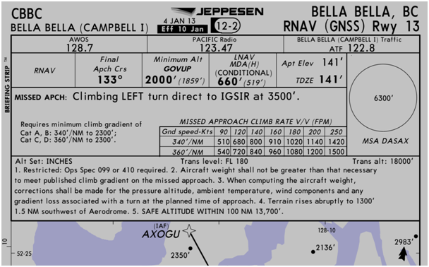 |
| Copyright Jeppesen® â€" Used By Permission â€" Not for Navigation |
Unfortunately, restrictions on chart distribution vary throughout the world. This means that the end-user of the data may or may not have a chart available in their normal subscription. They are not always able to easily determine whether or not they can fly the procedure. For example, in the United States only certain procedures that are deemed special instrument approach procedures (IAP) may have a restriction on their chart distribution. These procedures differ from an ILS CAT II/III or ILS SA chart that requires special authorization, which are developed as standard IAPs. Conversely, an IAP that has been developed as a special would have restricted chart distribution.
The FAA's Aeronautical Information Manual (AIM), section 5-4-8 provides the following explanation: "Special IAPs are also developed using TERPS (U.S. Standard for Terminal Instrument Procedures) but are not given public notice in the FR (Federal Registry). The FAA authorizes only certain individual pilots and/or pilots in individual organizations to use special IAPs, and may require additional crew training and/or aircraft equipment or performance, and may also require the use of landing aids, communications, or weather services not available for public use. Additionally, IAPs that service private use airports or heliports are generally special IAPs."
An example of a special IAP can be found at Eagle (KEGE) airport in Colorado. The standard IAPs available today are the GYPSUM5, MEEKER1, LDA DME RWY 25, and the RNAV (GPS)-D. However, as shown on the list below, there are additional procedures that are considered special with restricted chart distribution:
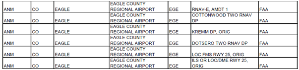 |
| Eagle, Colorado (KEGE) Special Instrument Approach Procedures |
Because a special procedure may have been developed for various reasons, the chart may only contain the word Special without any indication in the briefing strip as demonstrated by the Hayden ILS Z RWY-10:
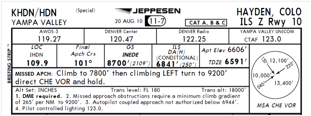 |
| Copyright Jeppesen® â€" Used By Permission â€" Not for Navigation |
The list above for the Eagle County Airport was retrieved from the FAA Special Instrument Procedures website, where a complete list of US procedures that have been designated as special can be accessed.
Transport Canada has developed a Restricted Instrument Procedures Advisory Circular AC 803-004 that can be downloaded here.
There are many procedures in the typical navigation database that require additional authorization to be flown. As RTCA states in DO-200A, "The ultimate responsibility of ensuring that the data meets the quality for its intended application rests with the end-user of that data." Therefore, it is imperative that before flying any procedure in the navigation database, the procedure name, waypoints, and constraints are verified with the appropriate chart.
Brock Graham is the Embraer, Hawker, NZ-2000, and Primus Elite™ Program Pilot. He can be reached via email at Brock.Graham@Honeywell.com
Engine Insights
HTF7000 Delayed and Booming Engine Starts
By Helmuth Eggeling
Some Challenger 300 operators have reported an occasional starting issue with their HTF7000-series turbofan engines. These operators have reported delayed light-offs (ignition) along with an audible bang or boom as a result of the late ignition, which can be disconcerting to the flight deck crew as well as the ground crew who are in the vicinity of the aircraft.
In order to understand the cause for the delayed light-offs and to develop a solution for this infrequent abnormality, Honeywell engineering thoroughly investigated several possibilities. Specialists from a variety of turbine engine disciplines evaluated the possibility of contaminated or inferior fuel, ignition system abnormality, validity of the electronic control unit (ECU) software algorithm, air turbine starter (ATS) system problems, as well as an investigation of the entire combustion system. No root cause of the occasional delayed/booming start has been discovered as of today as investigation is ongoing.
In spite of being unable to conclude the exact root cause, three known facts emerged from the study so far:
- Typically, the delayed light-off will occur when the engine is at or near ambient conditions and ambient temperatures that are cooler than standard.
- The problem tends to disappear when ambient temperatures increase.
- Using continuous ignition, the engine has demonstrated consistent starts without the audible boom.
Therefore, if delayed engine starts along with audible booms occur, Honeywell recommends performing subsequent engine starts using continuous ignition by setting the ignition switch to ON immediately before initiating an engine start. After the engine has successfully reached idle speed, it is important to turn the ignition switch to the OFF position.
Moreover, after completing 10 successful continuous ignition starts, it is recommended to perform a minimum of 4 normal auto starts before returning to continuous ignition starts. The purpose for this is to allow the full authority digital electronic control (FADEC) to perform the necessary checks of the ignition system and to ensure both ignition channels are operating properly. During continuous ON ignition starts, the FADEC is unable to perform these checks.
For more information, please see Service Information Letter D201204000044, which has been sent to affected operators and is also available to registered users by selecting "Search Technical Publications" here.
Helmuth Eggeling is a Honeywell Lead Test Pilot and Pilot Advisor. He can be reached at Helmuth.Eggeling@Honeywell.com or +1 (602) 231-2697 for questions on the above subject and other Honeywell engine topics.
Tools of the Trade
High-Definition, High-Efficiency LCD Flight Deck Upgrade
Operators of high-end business jets using select Honeywell flight decks can upgrade to the latest LCD-based retrofit system â"€ called Primus Elite â"€ providing significant improvements in situational awareness, display reliability and overall aircraft value.
The Primus Elite flight deck upgrade delivers the most sophisticated and user-friendly display retrofit available today, featuring powerful graphics, advanced features and the improved clarity of liquid crystal display (LCD) technology. Safety enhancements include geo-referenced aircraft positioning, Jeppesen electronic charts and maps, and video display capability, all enabled through a cursor control interface.
 |
Highly reliable LCD technology â"€ offering twice the reliability of cathode ray tube displays â"€ replaces existing CRTs, adding graphical capability to the flight deck but without the downtime, expense or additional pilot training needed with traditional display upgrades.
The Primus Elite flight deck also incorporates future growth capabilities for Honeywell's advanced family of IntuVue® 3-D weather radar systems and worldwide weather applications. The result is better route planning with smarter and faster decision making for weather avoidance while reducing pilot workload.
"This is a great opportunity for operators to move their legacy technology aircraft to the more efficient and powerful LCDs," said Dan Stockfisch, Honeywell Manger of Technical Sales.
In addition to improved clarity and reliability, LCDs offer video display capabilities such as onboard cameras including enhanced vision for takeoff, landing and terminal operations.
The system is already certified and in service on more than 200 aircraft including the Gulfstream GIV, GIV-SP and GV; Cessna Citation X, Embraer 600 and 650; Bombardier Global Express, Global Express XRS and Global 5000; and the Dassault Falcon 900EX and 900C.
"Since the Primus Elite flight deck upgrade is listed in the Blue Book, it not only increases mission efficiency but actually adds documented value to the operator's aircraft investment," Stockfisch said.
Please contact FTS@Honeywell.com for more information.
Global Data Center Update
Airport Information
By Kirk Waterhouse
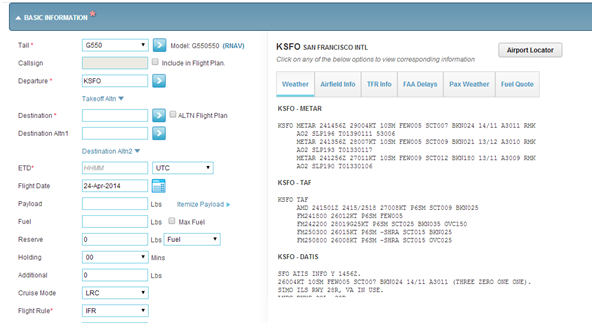
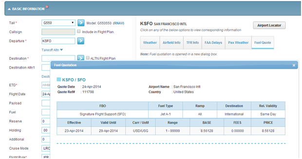
Global Data Center subscribers have access to detailed airport information as a flight plan is being created. This information includes weather, airfield info, temporary flight restriction info, FAA delays, passenger weather, and detailed fuel quotes. Each one of these options help pilots and dispatchers make informed decisions regarding their flight.
To access this data while creating a flight plan, enter the ICAO code for an airport in the departure, destination, or alternate field. On the MyGDC iPad App, airport information will display in a box below the airport field:
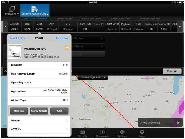 |
On MyGDC.com, click the blue arrow adjacent to any of the airport fields (![]() ). The airport information will be displayed on the right hand side of the page.
). The airport information will be displayed on the right hand side of the page.
Weather is displayed on the first tab, including METAR's, TAF's, D-ATIS (if available) and NOTAMS. This makes it easy to quickly decide if an alternate is required.
 |
The next tab is "Airfield Info", which will display detailed information about the airport, including an airport diagram. The airport diagram also displays the IFR approaches available for each runway.
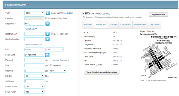 |
The next tab displays Temporary Flight Restrictions (TFRs). All TFR's within a 50 NM radius of the airport will be shown. This is followed by the FAA Delays tab, which shows delay programs occurring at the time of departure or arrival, and includes Ground Stops, Ground Delay Programs, and Departure Delays.
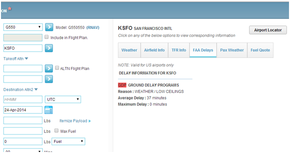 |
Finally, if the subscriber is registered for fuel quotes through the GDC's International Trip Services (ITS), discounted fuel prices will display for the airport selected.
 |
Have questions about this topic, International Trip Services, the Global Data Center, or datalink in general? Please contact FTS@Honeywell.com .
GDC Flight Data Specialist Kirk Waterhouse can be reached at Kirk.Waterhouse@Honeywell.com
Service Information Letter Briefing
Primus Epic® Database Loading SIL
Honeywell has worked with numerous operators who report having trouble loading their Primus Epic® databases (charts and navigation). These reports are generally limited to longer than expected load times, frequent FTP failures, and sometimes an inability to connect to the aircraft
Upon troubleshooting these reports, it was found that the PCMCIA cards, as well as the maintenance laptops, were infected with a computer virus. Although this had no impact on the Epic® system operation, this particular virus blocked communication over the LAN.
As a result, Honeywell has released SIL D201204000001 to provide a method of determining if the PCMCIA card and/or the maintenance laptop are infected with a virus. Once a virus has been found, it is important to quarantine both until they can be properly cleaned using antivirus software.
This SIL has been sent to affected operators and is also available to registered users through the Honeywell Technical Publications Portal. For more information, please contact AeroTechSupport@Honeywell.com.
Events and Training Calendar
2014 Events and Training
Honeywell's Flight Technical Services team travels all over the world to bring pilots the latest information on regulations, new technology, and Honeywell product updates. Through Pilot Breakout Sessions at Honeywell Operators Conferences, one-on-one training, entry into service support, and live webinars, Honeywell pilots are on a mission to keep operators informed.
 |
Most of this year's Operators Conferences include pilot breakout sessions with time for participants to ask questions and connect one-on-one with program pilots. Primary topics will include Mandates and Honeywell Solutions, Future Concepts, Service Information Letters, Global Customer Committee Project Overview, and a Pilots.Honeywell.Com Beta-Test Evaluation and Feedback Session. As always, all operator conferences are completely free. Please email FTS@Honeywell.com for more information.
Honeywell Flight Technical Services Q&A
Approval for LPV Outside of the US
By Jim Johnson
With EGNOS, Europe's Satellite Based Augmentation System (SBAS) up and running, many European states are publishing LPV approaches. To date, there are approximately 100 approaches available and the list is growing. Many operators have questions about whether or not they can take advantage of these procedures.
US-registered Part 91 operators are aware that there is no requirement to get a Letter of Authorization (LOA) from the FAA for an LPV approach in the US. However, the European Aviation Safety Agency (EASA) has issued guidance to European state aviation authorities requiring approvals for general aviation operators under European jurisdiction. Consequently, many US operators that are equipped and using LPV in the US are asking how they show compliance to fly LPV in Europe. Since each European state has its own aviation regulatory agency there is no all-encompassing answer. However, the following provides suggestions for those Part 91 operators that plan to use European LPV approaches. These suggestions were provided by several European regulatory authorities as suggestions for US Part 91 operators.
Background â€" Why the Difference
ICAO recommendations suggest that regulatory agencies require operational approvals for Performance Based Navigation (PBN)-type procedures (RNAV, RNP, LPV, etc.). EASA is following the recommendations for both commercial (US Part 121/135 equivalent) and non-commercial (US part 91 equivalent) operators of European-registered aircraft. The FAA, however, filed a deviation from the ICAO requirements and does not require a formal approval (LOA) for all PBN procedures. As a result, Part 91 operators aren't required to possess an LOA for LPV approaches.
Recommendations for US Part 91 Operators
When conducting LPV approaches in Europe or other foreign countries, operators should consider carrying documentation on board to show aircraft and flight crew compliance with LPV requirements. Airworthiness documentation may include AFM, STC or aircraft operating manual information stating the aircraft is approved for LPV. Flight crew compliance may include operating procedures/manuals, the MEL, and training records. This will be helpful to have if there is any question as to the capability to conduct these types of operations.
If there is any question or concern about a specific country, operators are encouraged to contact the regulatory authority directly. The following FAA website contains country "data sheets" which will have contacts to which specific regulatory questions can be addressed.
http://www.faa.gov/air_traffic/publications/ifim/country_info/country_information/
Summary
US Part 91 operators do not require an LOA to conduct LPV. And there are currently no FAA plans to issue them to US Part 91 operators. Therefore, when flying LPV approaches in Europe or other foreign countries, operators are encouraged to carry proof of aircraft and flight crew qualification and operational procedures for this type of operation and have it readily accessible to flight crewmembers should they be inspected or confronted with questions from local regulatory officials.
Senior Training Specialist Jim Johnson supports Honeywell Go Direct™ and regulatory issues for the Flight Technical Services team. He can be reached at James.Johnson2@Honeywell.com
Honeywell Pilots App
New Website and App Will Deliver Pilot Resources and Improve Communications
By Chris Van Cise
The Global Customer Committee has identified two areas where Honeywell can improve the customer experience: submitting of questions, issues, and feedback to Honeywell, and accessing pilot resources. In response, Honeywell is developing a new website and mobile app, which will debut this summer
Pilots who use Honeywell products and services will enjoy easy access to a wealth of training materials, manuals, videos, and other resources. They'll also be able to quickly submit questions and feedback to the Flight Technical Services team and Aerospace Technical Support (ATS). The goal is to give Honeywell customers "one stop shopping" in an easy to use interface.
 |
| Honeywell Pilots App Mockup |
Pilot Resources
Using the new app will be fast and intuitive. After identifying a make and model, pilots will be presented with carefully organized lists of resources, categorized by system. For example, to access the Integrated Avionics System Pilot's Guide, the user simply touches Integrated Avionics, and selects the Pilot's Guide from the menu. The guide can then be viewed, saved, or shared.
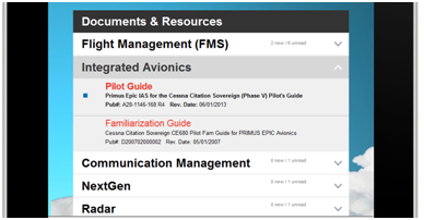 |
| Integrated Avionics System Resources for the Cessna Citation Sovereign |
Asking Questions
Sending a question or providing feedback to Honeywell is just as easy. Users simply click on the Contact Us button at the bottom of the app. This brings up a screen that allows them to submit general questions, suggestions, and provide technical issue reports. Submissions will go directly to the appropriate team within Honeywell.
 |
| Submitting a Question through the New App |
Created by Pilots, for Pilots
To make sure the new design is optimized for pilot use, Honeywell has engaged members of the Global Customer Committee to provide pilot input, testing, and validation throughout the development process. Pilots serving on the Global Customer Committee working group have shaped the interface, organization, and content selection process to ensure operators' needs are met by the new app.
This project is one of many great ideas under development by the Global Customer Committee. For more information on joining or making contributions to the GCC, please visit their website.
Training Specialist Chris Van Cise supports the Global Data Center, data link, and technical publications for Honeywell Flight Technical Services. He can be reached at Christopher.VanCise@Honeywell.com
Global Data Center Update
MyGDC iPad® App Version 3.0
By Kirk Waterhouse
The Global Data Center is proud to announce the release of version 3.0 of the MyGDC iPad® App. Several new features have been added, including: Runway Analysis and Weight & Balance powered by APG (Aircraft Performance Group), enhanced European route options, eAPIS submissions for international departure and arrival notifications, and enhancements to graphical weather overlays.
Runway Analysis and Weight & Balance Reports
The newly added Runway Analysis and Weight & Balance reports can be generated manually or associated with a flight plan. Whether generated from the app, or on MyGDC.com, each report is easy to compute and read.
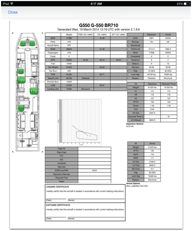 |
| Weight and Balance Report |
Pilots will get the most out their Runway Analysis and Weight and Balance reports, and be able to view them offline, by adding them to a trip kit. Trip kits store flight plans, weather, and other data for later use on the iPad®, for printing, or for delivery via email. By creating a trip kit, pilots can have everything they need for dispatch in one package.
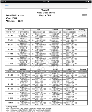 |
| Runway Analysis Report â€" Demonstration Use Only |
The Trip Kit can be created after all planning is complete. Once the kit is downloaded, it can be printed or emailed.
Look for more updates on the new MyGDC App features in the coming months. For more information about these features or for aditional training, please contact the Global Data Center.
Honeywell Global Data Center
Toll Free (US & Canada): 1-888-634-3330
International Customers: +1 425 885-8100
Fax: +1 425-885-8930
Email: gfo@mygdc.com
GDC Flight Data Specialist Kirk Waterhouse can be reached at Kirk.Waterhouse@Honeywell.com
Go Direct™ Briefing
Levels of RNAV and RNP Explained
By Reggie Crocker
The different levels of RNP and how they apply to various aircraft operations create a lot of questions around the hangar. This month, the Go Direct™ Briefing will discuss these levels and how they apply to various aircraft operations.
RNAV and RNP are a part of Performance Based Navigation (PBN) which defines an aircraft's capability to navigate using a defined performance standard. RNAV means Area Navigation, while RNP is Required Navigation Performance. To keep the two separate, it's important to remember that RNP is a type of RNAV where on-aircraft monitoring and alerting are added to the area navigation. In other words, RNAV may take the aircraft to the destination over a defined route, while RNP will do the same with the addition of monitoring the navigation performance and alerting the crew if there is a problem with navigation accuracy.
How much accuracy is needed?
When RNAV and RNP terms are referenced they are typically followed by a number. That number is the expected accuracy in nautical miles. Requirements exist today for RNAV 1, RNP 1, RNAV 2, RNP 4, RNAV 5, and RNP 10. Additionally, approach procedures exist which have specific accuracy requirements. These included RNAV (GPS), RNAV (GNSS) and RNAV (RNP AR). The most common example is RNAV (GPS). This is a GPS, or Global Navigation Sensor System (GNSS) based approach procedure.
The following table lists the various RNAV and RNP criteria, the FAA Advisory Circular that defines the requirements for each, and the FAA Operational Specification (OPSPEC/LOA) that is required for an operator to utilize such an RNAV or RNP procedure.
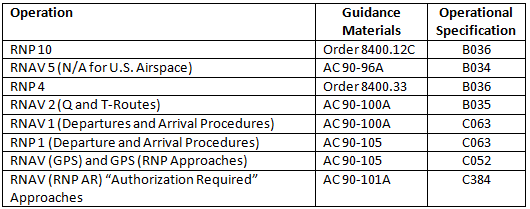 |
Here's a brief explanation of applications for each of the above accuracies:
RNP 10 â€" Used for oceanic and remote operations. RNP 10 has a 50 nm lateral and longitudinal separation between aircraft.
RNAV 5 â€" Also known as BRNAV (Basic RNAV). Utilized in European airspace.
RNP 4 â€" Oceanic and remote operations. RNP 4 allows closer aircraft spacing of 30 nm and may also require communications and surveillance capabilities in the aircraft.
RNAV 2 â€" Enroute segments for Q routes and T routes.
RNAV 1 â€" Departure procedures and arrival procedures (SIDS/STARS) with 1 nautical mile navigation accuracy required.
RNAV (GPS) â€" A GPS based approach procedure with 0.3 nm accuracy.
RNAV (RNP AR) â€" An RNP AR based approach procedure with at least 0.3 nm accuracy down to 0.1 nm accuracy dependant on the approach minima. Aircraft and crew Authorization is required due to tighter procedure design and aircraft capability requirements.
RNP 1 (SIDs and STARS) â€" Although not in the RNP soup today, RNP SIDS and STARS are being planned and may enter our world of Performance Based Navigation published procedures in the near future.
Honeywell Go Direct™ offers assistance to operators looking to take advantage of RNP AR approaches. Please email FTS@Honeywell.com for more information.
Engineer Reggie Crocker supports Honeywell's Go Direct™ and Navigation Database services. He can be reached via email at Reginald.Crocker@Honeywell.com
Service Information Letter Briefing
Common Waypoints in SIDs and STARs
By Jeff Holt
Over the past several years, the National Airspace System (NAS) has seen an increase in Standard Instrument Departures (SIDs) and Standard Terminal Arrival Routes (STARs) that have much longer distances than traditional terminal routes. Subsequently, many routes between city pairs can begin with a SID and end with a STAR with no enroute phase of FMS flight.
Most Honeywell Flight Management Systems rely on a certain set of criteria in order to perform normal VNAV operations. In this case, the FMS relies on having all three phases of flight loaded into the flight plan for it to properly transition to the various VNAV modes. However, when a flight plan is loaded where there is a common waypoint on the SID and STAR, the FMS does not see any enroute phase of flight. When this occurs, the FMS is not capable of descending in VNAV mode until the last waypoint of the SID has sequenced.
There are several operational mitigations that will allow the FMS to recognize that it is no longer in CLB mode even though it is still on a SID.
- The most common method is to select the "D" (descent) mode on the waypoint where cruise altitude is achieved. In this example, CYPRS shows the correct cruise altitude of 22,000' but it is still in CLB mode. Therefore, the first DES mode shown is at BENET which is incorrect since the FMS should show DES mode prior to achieve the crossing restriction.
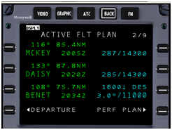
- By placing a D on the LSK where level off has been achieved, the FMS will then honor the altitude restriction at BENET
 |
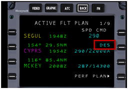 |
Flight crews should be aware that the FMS may not command a descent at the proper distance prior to a crossing restriction whenever a SID and STAR share a common waypoint. By inserting a "D" command at the waypoint where cruise altitude has been achieved, the FMS will be able to properly calculate a Top of Descent and correctly descend and achieve the stated crossing restriction.
For more information on this subject, please read the full text of SIL D201401000013. This SIL has been sent to operators and is also available to registered users through the Honeywell Technical Publications Portal.
Jeff Holt supports Dassault operators and is the Manager of Pilot Training for Honeywell Flight Technical Services. He can be reached at Jeffrey.Holt@Honeywell.com
Tools of the Trade
In-flight Internet
| March's Aircraft Electronics Association convention brought an array of people, products and presentations that made the event a successful one for attendees and exhibitors. In the increasingly important arena of in-flight internet, BendixKing by Honeywell unveiled the BendixKing AeroWave 100, a new high-speed Internet solution. Not only is the technology in the AeroWave 100 new, but so are the simple, easy to understand service plans based on hours of use. Unlike other plans that charge by how much data was used, the AeroWave 100 makes it easy for pilots, passengers and business owners to stay connected to the world below during flight without worrying about costs. |
 |
By leaving data charges behind, AeroWave 100 users can easily send and receive emails, surf the web and stay connected while airborne. Please visit the AeroWave 100 website, or email FTS@Honeywell.com for more information.
Tools of the Trade
In-flight Internet
March's Aircraft Electronics Association convention brought an array of people, products and presentations that made the event a successful one for attendees and exhibitors. In the increasingly important arena of in-flight internet, BendixKing by Honeywell unveiled the BendixKing AeroWave 100, a new high-speed Internet solution.
Not only is the technology in the AeroWave 100 new, but so are the simple, easy to understand service plans based on hours of use. Unlike other plans that charge by how much data was used, the AeroWave 100 makes it easy for pilots, passengers and business owners to stay connected to the world below during flight without worrying about costs.
By leaving data charges behind, AeroWave 100 users can easily send and receive emails, surf the web and stay connected while airborne. Please visit the AeroWave 100 website, or email FTS@Honeywell.com for more information.
Events and Training Calendar
2014 Events and Training
Honeywell's Flight Technical Services team travels all over the world to bring pilots the latest information on regulations, new technology, and Honeywell product updates. Through Pilot Breakout Sessions at Honeywell Operators Conferences, one-on-one training, entry into service support, and live webinars, Honeywell pilots are on a mission to keep operators informed.
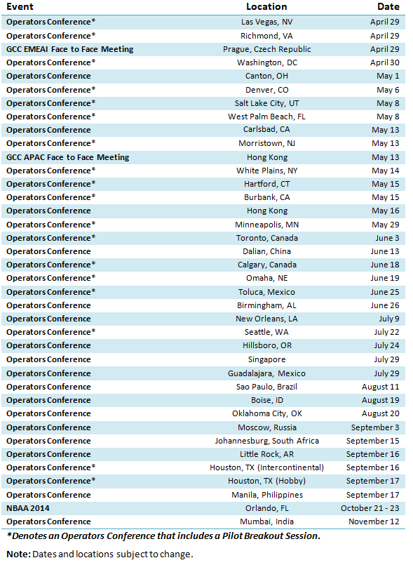 |
Most of this year's Operators Conferences include pilot breakout sessions with time for participants to ask questions and connect one-on-one with program pilots. Primary topics will include Mandates and Honeywell Solutions, Future Concepts, Service Information Letters, Global Customer Committee Project Overview, and a Pilots.Honeywell.Com Beta-Test Evaluation and Feedback Session. As always, all operator conferences are completely free. Please email FTS@Honeywell.com for more information.
Engine Insights
Effect of Spinner Shape on Ice Collection
By Helmuth Eggeling
Editor's Note: The Direct-TO Newsletter is excited to announce a new section devoted to Honeywell Engines and APUs. Featuring articles written by Honeywell Test Pilot and Pilot Advisor Helmuth Eggeling, Engine Insights will tackle mechanical issues from a pilot's perspective.
Helmuth flies Honeywell's Boeing 757 Flying Test Bed, or FTB, based at Phoenix Sky Harbor Airport in Arizona. In addition to testing turbine engines during the R&D and certification phases, and performing avionics R&D and product demonstration flights, Helmuth has been the Honeywell Engines Pilot Advisor for over 23 years.
In his Pilot Advisor role, Helmuth supports internal customers (Honeywell Engineering, Field Service and Product Integrity) and External Customers (aircraft owners and operators, airframe manufacturers, training organizations and military customers) by representing the pilot's perspective in engine operations.
Besides participating in the writing of Operating Information Letters (OILs) and Pilot Advisory Letters (PALs), Helmuth has authored engine operational tips and techniques for a variety of airframe specific publications, including Flight Levels for the Twin Commander, and MU-2B Magazine.
In an effort to provide customers with a direct connection to all Honeywell technical support tools, Helmuth's role as pilot advisor for Honeywell engines was recently integrated into the Marketing &Product Management Flight Technical Services group, which allows more pilots to benefit from his insights through publications like Direct-TO.
| From time to time, Honeywell receives interesting questions from pilots or training center instructors, such as "Is it true that the TFE731 engine spinner has been designed to wobble in order to shed ice?" |  |
The following is the result of extensive research within Honeywell's engineering library and brain trust to "shed" some light on this myth.
It's important to point out from the beginning that no engineer would design a turbine fan rotating at nearly 10,000 RPM to be subjected to an engineered vibration. The side loads acting upon the shaft bearings would be unacceptable. In fact, much of their engineering efforts go into creating a design that exhibits the least possible imbalance. Furthermore, a wobbling spinner would be unnecessary during the 90 percent or more of flying that is in an ice-free environment.
The evolution of turbofan spinners, from elliptical to today's conical designs, demonstrates why modern spinners do not normally require provisions for anti-icing.
The original TFE731-2 engines used to incorporate heated elliptical spinners (Fig. 1 and Fig. 2). These spinners, when heated, were certified for operations in icing conditions. Bleed air is extracted from the plenum surrounding the combustor and ducted internally to the inner surface of the spinner, finally exhausting into the fan airstream just forward of the fan blades.
The ALF502/LF507 engine series uses an oil-heated elliptical spinner that was certified for icing operation in 1976. In 1977, the first investigation into an unheated conical spinner (Fig. 1 and Fig. 3) was conducted.
 |
| Fig. 1 Elliptical and Conical Spinners |
 |
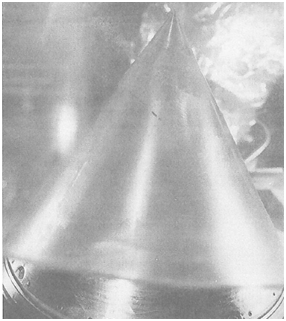 |
| Fig. 2 Elliptical Spinner |
Fig. 3 Conical Spinner |
A series of unheated elliptical and conical spinner icing tests revealed that the ice accumulation on the elliptical spinner occurred at a significantly higher rate (Fig. 4) than on the conical spinner (Fig. 5). It was also observed that major shedding did not occur on the elliptical spinner during the 3-minutes ice accretion period, whereas ice accretion at the tip of the cone on the conical spinner shed continuously (Fig. 6).
 |
 |
| Fig. 4 Elliptical Spinner Accumulates a Significant Amount of Ice |
Fig. 5 Conical Spinner Accumulates Significantly Less |
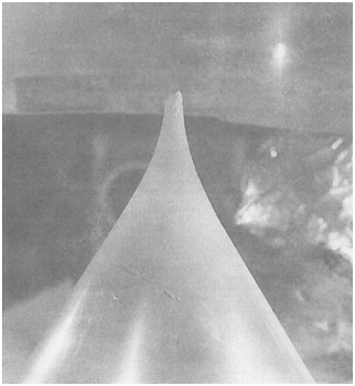 |
| Fig. 6 Ice built up quickly and then the tip broke off. This cycle repeated approximately every 15 seconds. |
It was determined that continuous shedding on the conical spinner is due to the fact that any thin ice build-up results in a not perfectly centered, needle like ice structure (Fig. 5). This generates a slightly eccentric rotation and imbalance, resulting in the ice to break off (Fig. 6), then a new ice build-up, followed by another ice break off about 15 seconds later, ad infinitum, as long as icing conditions exist.
According to results from the Conical Spinner Icing Tests, it was determined that the conical spinner does not require anti-icing provisions by proving that ice accumulated and removed in all cases during the tests weighed significantly less than the ice balls used in engine hailstone ingestion tests. The engine therefore meets the FAR Part 33 icing certification requirements.
It appears that the perceived wobble is due to the fact that ice builds up slightly off-center while the spinner rotates perfectly centered. The spinner itself remains wobble-free.
The information contained herein is based on and quoted from the "Anti-Ice Spinner Icing-Test" Report by Garrett Turbine Engine Company dated in September 1977.
Both spinners were exposed to a maximum intermittent icing condition in the icing tunnel.
- Spinner speed: 4,228 rpm
- Spinner stagnation point: 6 inches from single spray nozzle
- 20μ water droplet at 32°F when impinging on spinner
Helmuth Eggeling is a Honeywell Lead Test Pilot and Pilot Advisor. He can be reached at Helmuth.Eggeling@Honeywell.com for questions on the above subject and other Honeywell engine topics.
Honeywell Flight Technical Services Q&A
Temperature Compensation â€" Part 3 of 3
By Brock Graham
In the previous November and February editions, temperature compensation, why it is used, and a basic "how to" was discussed. Part three of this series will look at the calculator function of the FMS temperature compensation feature. As discussed in part two, the FMS will modify the encoded altitudes for waypoints on a segment of an approach, or in some installations on a departure. Here the RNAV Rwy 15 into Bangor Maine, KBGR is used as an example; the temperature at the airport is -18 degrees C.
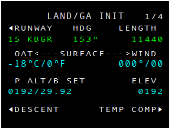 |
| RNAV Rwy 15 KBGR LAND/GA INIT Page |
 |
| Altitude Constraints for the RNAV Rwy 15 KBGR |
The crew must load the approach, set the landing temperature in the landing init page, and review and activate the temperature compensated altitudes. The crossing altitude at IKEXE now shows 3,360A instead of 3,000A. UMAIN is similar with 2,350A replacing 2,100A. The RW15 Missed Approach Point (MAP) altitude is then corrected to 250A. These new altitudes now provide the corrected vertical path.
However, if during the approach the altitude preselect is set to the appropriate minimums from the chart, that minimum is not compensated. This is where the TEMP COMP Calculator comes in.
The calculator can be found on the last TEMP COMP page. It is important to note that the temperature displayed on the top row comes from the temperature that was initially set on the LAND/GA INIT page. Simply type in the desired Minimum Descent Altitude (MDA) or Decision Altitude (DA) to calculate the compensated MDA or DA.
Note: For EASy II operators, the calculator is available on the Landing Data tab.
 |
| Temperature Compensation Calculator |
 |
| EASy II Temperature Compensation Calculator |
For the NZ and EPIC example, using LNAV minimums of 720', the outputted compensated altitude is 787'. For the EASy II image, 2,000' is entered (as an example) and the compensated altitude result is 2,250'.
Some pilots have asked why the FMS doesn't automatically make this adjustment to the MDA or DA for them. A careful look at the vertical profile for procedures will help explain.
The approach procedure is coded in the navigation database as a series of instructions to construct a lateral path to navigate the aircraft from point A to points B, C, and so on. This is fairly simple to understand; however, when a vertical element is added, it's important to understand that the FMS makes vertical calculations differently.
The vertical path must begin somewhere. For a straight in approach, the runway is used as a waypoint and the altitude coded into the procedure is most often the Touch Down Zone Elevation (TDZE) plus the threshold crossing height (50' in this case). This is the starting point for VNAV calculations as seen on the chart the TDZE is 192'+50'=242' (as seen coded at runway 15). Now imagine a glideslope projecting from this point toward the final approach fix. We can see this on the profile view of the chart and in this case. This vertical path, on its way to the FAF, will cross first through several layers of altitude. First it crosses the LPV, then the LNAV/VNAV, then LNAV, and finally the Circle-To-Land minima.
 |
| KBGR Runway 15 RNAV Approach Image © Jeppessen® - Used by Permission. Not for Navigation |
Now imagine being the procedure designer. Which of these altitudes would make the best waypoint? For the RNAV 15 at KBGR, if all of these intersections of the vertical path and an altitude layer were converted to waypoints there would be four waypoints in very close proximity. Making things worse, remember that aircraft categories will need to be considered too. It would be far too cluttered and confusing. Therefore, the procedure design provides strict requirements as to what altitude is encoded at the missed approach point.
For more information on hot and cold temperature limitations, please refer Chapter 5-4-5 in the FAA Aeronautical Information Manual.
Brock Graham is the Embraer, Hawker, NZ, and Primus Elite Program Pilot. He can be reached via email at Brock.Graham@Honeywell.com
Honeywell Flight Technical Services Q&A
Place/Bearing/Distance Placement Using a Runway
By John Dano
Using the Place/Bearing/Distance (PBD) method is a simple way for flight crews to insert a pilot-defined waypoint at a bearing and distance from another waypoint in the navigation database. For example, if a pilot wanted to put in a waypoint 30NM from PXR at the 064 degree bearing, they would enter PXR/064/30.
Things get a bit more difficult when using a runway to define a PBD waypoint. Honeywell has discovered that many operators believe that the FMS will use the departure end of the runway as the beginning point, which is not correct. Instead, the FMS will use the runway approach end threshold as the anchor point for the PBD. In the example shown in Figures 1 and 2, a waypoint is added to a flight plan that does not contain a Standard Instrument Departure procedure (SID). This example could be used to comply with an ATC request or to meet certain departure criteria, including noise abatement procedures.
 |
| Figure 1. FMZ2000 CDU with the 2NM PBD (*PBD03) |
 |
| Figure 2. Approximate location of KDVT.RW07R/074/2 |
In this example, the flight crew has been instructed to maintain the runway heading for 2NM beyond the departure end of the runway. The crew has used the PBD method to insert a waypoint (*PBD03) using 2NM ( KDVT.RW07R/074/2). This has resulted in a waypoint that is 2NM from the runway approach end threshold, but only .8 NM from the departure end of the runway, which is 8197' in length.
The takeaway here is that flight crews will need to add the length of the runway to the distance, or use a different waypoint (VOR/NDB/named waypoint/departure end of runway) as the anchor point of the PBD. Otherwise, the PBD waypoint could be a mile or more away from where the crew and ATC expect it to be.
For help with this and other FMS topics, please email TalkFMS@Honeywell.com.
Tools of the Trade
Increasing Situational Awareness
By Brandon Burton
In 2003, Honeywell developed the Runway Awareness and Advisory System (RAAS). It was the first system providing improved flight crew situational awareness to help minimize the potential of runway incursions and excursions.
The RAAS system was developed as a "Talking" system. It issues more than a dozen different alerts by using aural warnings that are triggered by utilizing runway information contained in the Enhanced Ground Proximity Warning System (EGPWS) database. It is important to note that even if the flight crew is aware of their position, the system will issue alerts advising the flight crew of a risk, such as approaching a runway.
More recently, Honeywell has developed SmartLanding™ and SmartRunway™, which provide enhancements to RAAS including visual indications and additional aural warnings.
 |
| In Air RAAS â€" Identifying the Runway |
Another product developed to greatly increase situational awareness is the Honeywell Synthetic Vision System (SVS). SVS greatly reduces the likelihood of Controlled Flight into Terrain (CFIT) and is available on a number of Honeywell equipped aircraft platforms. The system simplifies instrument flight by replicating cues basic to visual flight, and integrates existing Primary Flight Display (PFD) data with a day Visual Meteorological Conditions (VMC) graphics. This creates an ambient, natural, and continuous presentation.
SVS improves flight crew safety by enhancing their knowledge of the surrounding terrain and obstacles. The imagery generated on the PFD is derived from a combination of the EGPWS and Flight Management System (FMS) navigation databases.
 |
| SmartView™ Honeywell Synthetic Vision System (SVS) |
Operators who equip their aircraft with both RAAS and SVS greatly increase the flight crew's situational awareness; ultimately increasing safety. Occasionally, operators may experience a variation with runway numbering between the RAAS generated audio alerting system, and the runway number displayed on the synthetic vision. This is because the graphical runway generated by the SVS is derived from the FMS Navigation database, which is updated every 28 days. As previously mentioned RAAS utilizes the EGPWS database to generate the runway number aural alert and is updated less frequently than the FMS database; typically three to four times a year. While operating at an airport with recently amended runway numbers, operators may experience this variation between the two systems.
For more information about RAAS, SmartView®, and other technologies that enhance crew situational awareness, please email the Flight Technical Services team at FTS@Honeywell.com.
Training Specialist Brandon Burton covers data link, surveillance, the Global Data Center, and Falcon 900 EASy and EASy II. He can be reached via email at Brandon.Burton@Honeywell.com
Service Information Letter Briefing
PC-12NG - GPS Initialization Times with Apex® Builds 8.6 and 8.7
Honeywell has published Service Information Letter (SIL) D201312000062 to address longer-than-expected initialization times for some PC-12NG aircraft loaded with Apex® Build 8.6 or 8.7. Upon start-up, the GPS receiver may not receive the present position data needed, so GPS initialization can take longer than expected.
The SIL provides an interim solution and instructions from an excerpt of the Primus Apex Integrated Avionics System Pilot's Guide for the PC-12NG.
The interim solution includes updating the flight management system (FMS) position with an airport identifier (reference waypoint). This will result in faster GPS initialization from the KGS 200 Global Navigation System Sensor Unit (GNSSU). This step can be taken in lieu of waiting several extra minutes for the GPS position to become active on its own.
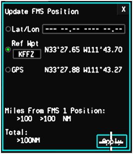 |
| Update FMS Position - Reference Waypoint KFFZ Selected |
Please reference the original SIL for more information. Replacement copies can be downloaded from the Technical Publications Portal. Questions? Please contact TalkFMS@Honeywell.com.
Events and Training Calendar
2014 Events and Training
Honeywell's Flight Technical Services team travels all over the world to bring pilots the latest information on regulations, new technology, and Honeywell product updates. Through Pilot Breakout Sessions at Honeywell Operators Conferences, one-on-one training, entry into service support, and live webinars, Honeywell pilots are on a mission to keep operators informed.
 |
Note: Dates and locations subject to change.
Most of this year's Operators Conferences include pilot breakout sessions with time for participants to ask questions and connect one-on-one with program pilots. Primary topics will include Mandates and Honeywell Solutions, Future Concepts, Service Information Letters, Global Customer Committee Project Overview, and a Pilots.Honeywell.Com Beta-Test Evaluation and Feedback Session. As always, all operator conferences are completely free. Please email FTS@Honeywell.com for more information.
Honeywell Flight Technical Services Q&A
Temperature Compensation â€" Part 2 of 3
By Brock Graham and Brandon Burton
The November edition of the Direct-TO Newsletter discussed what temperature compensation is and why it is needed. This edition will discuss how to utilize the built-in TEMP COMP features included in the recent software releases for Honeywell Epic™, NZ, and EASy II™ Flight Management Systems. As with all systems, operators are encouraged to consult the appropriate regulations, operating procedures, and their Approved Flight Manual before using temperature compensation. The design is such that there are a few steps required to properly use temperature compensation and this article is simply a high level discussion of that functionality.
Temperature compensation on Honeywell platforms allows the pilot to easily compensate VNAV altitude constraints during operations in extremely hot or cold temperatures. Recall that in cold weather, cold air is condensed and the true altitude of the airplane will be lower than the indicated altitude. Conversely, in hot air the true altitude of the airplane will be higher than the indicated altitude. Extreme temperatures can have a significant impact on indicated versus true altitude. The temperature compensation function within the FMS is designed to modify the encoded waypoint altitude values.
The FMS can apply temperature compensation to altitude constraints on all waypoints in departure (on certain installations), approach, approach transition, and missed approach segments of a flight plan. When temperature compensation has been applied to an active flight plan, it ensures the aircraft will fly (while in VNAV) the published altitudes even when non-standard temperatures exist.
The FMS temperature compensation logic modifies an altitude constraint by adding or subtracting a calculated correction value to or from the indicated altimeter value in non-ISA conditions. The following is the basic sequence pilots will follow to utilize temperature compensation:
- Ensure that the FMS has the temperature compensation activated on the SETUP or FLIGHT CONFIG page.
- Enter a departure and/or approach procedure into the active flight plan.
- Enter the takeoff or landing surface temperature in the TAKEOFF or LAND/GA INIT, or LANDING CONFIG pages. This will display a TEMP COMP prompt from which the pilot can review and ACTIVATE or COMPUTE the FMS calculated altitudes into the flight plan. For EASy II™ operators, the calculations will be applied to the waypoint automatically on the INAV flight plan display after the compute icon has been pressed.
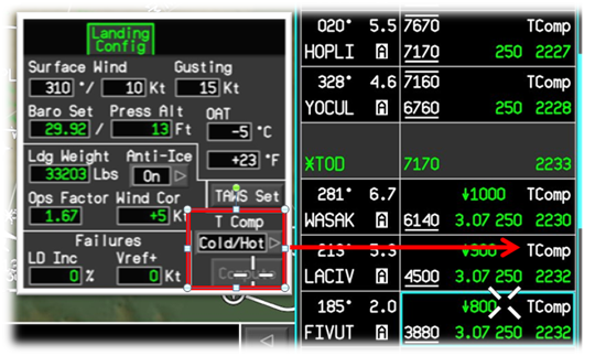 |
| Landing Config and Temperature Compensation on EASy™ |
For Epic™ and NZ™ users, the TEMP COMP pages are divided into three columns. The left column lists the names of the waypoints in the flight plan. The middle column lists the database altitude constraints corresponding to the waypoints. Finally, the right column lists the corresponding temperature compensated altitude values. If a waypoint does not have a navigation database altitude constraint encoded, the corrected altitude fields will remain blank. For waypoints with window altitude constraints, only the lower constrained altitude information is displayed on this page. The TEMP COMP pages permit the pilot to review and activate or cancel the temperature compensation made to the active flight plan. The TEMP COMP page title includes the temperature used to make the calculations as entered by the pilot.
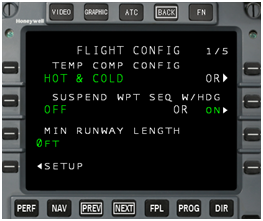 |
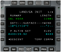 |
| NZ 6.1 FLIGHT CONFIG Page | NZ 6.1 LAND/GA INIT Page |
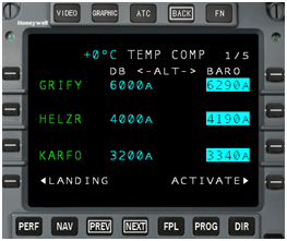 |
| NZ 6.1 TEMP COMP Page |
Data displayed on the TEMP COMP pages is automatically updated when there are flight plan modifications (lateral or vertical) to the approach, approach transition, or missed approach waypoints. Specifically for window constraints, once activated the FMS computes the correction for the lower altitude of the window constraint first, and then applies that correction to both the lower and upper window altitudes. It is very important to note that the system will not allow pilot entered altitude constraints to be automatically compensated.
Once activated, the ACTIVE FLIGHT PLAN will display the temperature compensated altitudes from the Navigation Database in reverse video for pilot awareness. It is important to note that LPV approaches use a geometric glide path which is not affected by extremely cold or hot temperatures. However, temperature compensation can be used in conjunction with LPV approaches to aid with ensuring that the barometric altitude is the same as the true altitude at the FAF to ensure that the LPV path will capture smoothly.
Temperature compensation cancellation will occur when any of the following take place:
- An approach, approach transition (if any), and missed approach (if any) are deleted or the destination airport is changed.
- The aircraft reaches the departure transition altitude or sequences the last SID waypoint.
- The departure procedure is deleted.
The scratchpad message TEMP COMP CANCELLED is displayed when Temperature Compensation mode is canceled.
Look for part three of this article next month, which will address the TEMP COMP Calculator and its importance.
Brock Graham is the Embraer, Hawker, NZ, and Primus Elite Program Pilot. He can be reached via email at Brock.Graham@Honeywell.com
Training Specialist Brandon Burton covers data link, surveillance, the Global Data Center, and Falcon 900 EASy and EASy II. He can be reached via email at Brandon.Burton@Honeywell.com
Global Data Center Update
GDC Launches International Trip Support
Global Data Center subscribers now have access to fully integrated International Trip Support (ITS). This new service is easily accessible online at MyGDC.com, or through a quick phone call to the GDC. Formed in partnership with worldwide flight support provider Jetex, ITS adds several new features to the familiar GDC interface.
International Handling Services
ITS is a fully integrated GDC service, powered by Jetex's expertise in worldwide flight support. Clients will benefit from Jetex's experience with international handling and its staff located worldwide. A complete suite of international planning and handling services are available, including permits, customs, fuel, hotels, ground transportation, and catering. Jetex has a commanding presence in several key growth regions, including a network of supervisors based across Africa, and an office in Beijing. The GDC will remain the primary point of contact to arrange and manage these services.
Discount Fuel Worldwide
The GDC also offers discounted fuel with FBOs around the world through this new partnership. GDC customers can access fuel information under the Airport Information tab on MyGDC.com. Fuel quotes are quick and easy to get; just enter an ICAO airport identifier and select Go. VAT compliant invoicing is available for operations throughout Europe.
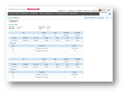 |
| Web-based ITS Portal on MyGDC.com |
Customers interested in ITS services can submit a request under the International Trips tab on MyGDC.com. The ITS portal is fully integrated into the website and follows a similar layout and functionality to other tools on the GDC website.
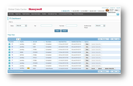 |
| International Trip Dashboard on MyGDC.com |
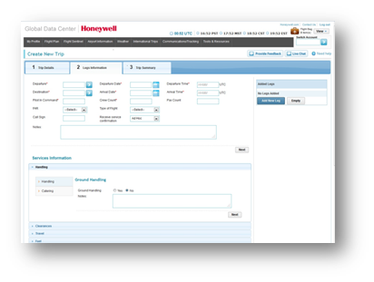 |
| New Trip Request |
In addition to requesting handling, catering, permits, slots, hotel, and ground transportation, users can make special requests in the Notes field available in each section.
For a trip cost estimate provided within 48 hours or to learn more about the GDC's International Trip Support, please contact the GDC using the numbers below or e-mail its@mygdc.com.
Honeywell Global Data Center
Toll Free (US & Canada): 1-888-634-3330
International Customers: +1 425 885-8100
Fax: +1 425-885-8930
Email: gfo@mygdc.com
Honeywell GNS-XLS
GNS-XLS Capabilities
By Mike Faulkner and Dale Carter
Honeywell often receives requests from customers wanting to know the capability of the GNS-XLS installed in their aircraft. To determine these capabilities, the Limitations Section of the Aircraft Flight Manual or Flight Manual Supplement that corresponds to the installation of the GNS-XLS, or a Letter of Authorization (LOA) for operations in Special Use Airspace must be consulted.
The table below shows the performance capability of the different GNS-XLS part numbers. The table only provides capability of the GNS-XLS Flight Management System. It is not an indication that the GNS-XLS, as installed in your aircraft, has been approved to fly the procedures stated in the table.
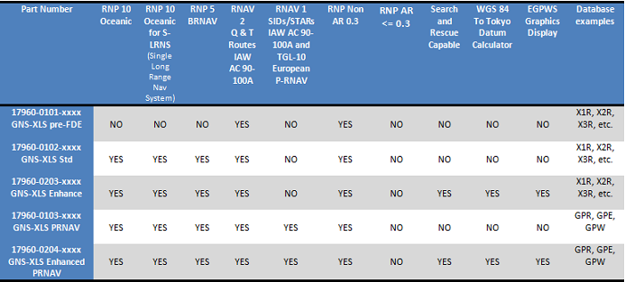 |
To determine a GNS-XLS part number, start by going to the Initialization page. Next, line select 4 Left. The part number will display in the bottom left corner as shown in the graphic below:
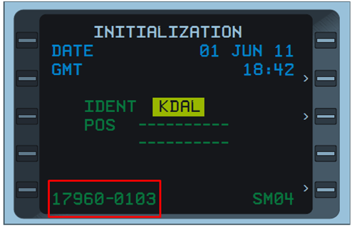 |
| Part Number on GNS-XLS Initialization Page |
The Technical Operations Center (TOC) is available 24/7 to assist operators with questions about their electronics and mechanical systems. Please visit the TOC website for more information.
Senior Technical Service Specialist Mike Faulkner can be reached via email at Mike.Faulkner@Honeywell.com.
Senior Product Support Engineer Dale Carter can be reached via email at Dale.Carter@Honeywell.com.
Go Direct™ Services
Arrival and RNP AR Approach Combination
By Reggie Crocker
RNP AR Approaches are unique in that they allow aircraft paths to be closer to terrain, obstacles, and restricted airspace than other approach types. One of the tools used to accomplish this is the defined arc path, or RF (Radius to Fix) leg. One of the rules around RF legs is that the preceding leg cannot be a heading leg, and trained RNP crews know not to accept a heading to intercept an RF leg.
When an arrival procedure and approach are loaded into the FMS, the system will look for common waypoints and ‘meld' the two procedures together. This is done to remove additional waypoints that would exist in the flight plan if the complete arrival and approach were put together.
Recently, a problem has been identified when certain RNP AR approaches with RF legs are combined with STARs that share waypoints with the approach. Service Information Letter D201308000050, Published September, 2013, explains this issue in detail. In this instance, the arrival procedure ends with a pair of waypoints with ATC guidance planned after the arrival ends. Those two waypoints are also used as an initial fix to an RNP AR procedure with an RF leg turn to final. When the system combines the two procedures, a heading precedes the RF leg and the system identifies this as an illegal combination - the RF leg is removed.
The example shows how this can occur at KSDF on the MAUDD2 Arrival to Runway 17L:
| The arrival ends with waypoints KAEDN and STYKR to a heading leg, vectors expected. |
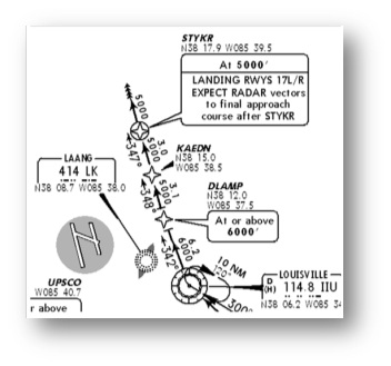 |
| Image © Jeppessen® - Used by Permission. Not for Navigation. |
| The RNP AR approach RNAV (RNP) Z RWY 17L has an initial fix of KAEDN to STYKR followed with an RF leg. |
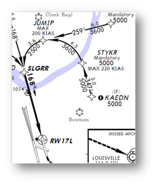 |
| Image © Jeppessen® - Used by Permission. Not for Navigation. |
| The FMS aligns the waypoint pair KAEDN and STYKER, and then sees the heading leg followed by the RF leg. The RF leg will be removed from the flight plan. |
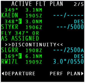 |
| Flight Plan Showing RF Leg Removed |
This problem is rare and has only been identified in a few airports. If it is observed, the crew can select a different transition or select a different approach to remove the problem. As a reminder, the flight plan as entered in the FMS should always be checked against the charts.
The Gulfstream G450 and G550, along with the Falcon 900 EASy II, are certified for RNP AR. For more information on how to obtain operational approval, please contact Jim Johnson with Go Direct™.
Engineer Reggie Crocker supports Honeywell's Go Direct™ and Navigation Database services. He can be reached via email at Reginald.Crocker@Honeywell.com.
Service Information Letter Briefing
Heading Legs on Departure Procedures and Missed Approaches
In an effort to inform pilots about FMS heading versus track behavior, a Honeywell Service Information Letter (SIL) has been published. SIL D201210000071 discusses how departure and missed approach procedures with "fly heading" or "climb heading" legs are flown by business and general aviation aircraft using Honeywell FMS.
The SIL recommends that pilots understand this functionality, and maintain vigilance when operating in close proximity to other aircraft. Additional pilot recommendations are provided by the SIL, which can be found here.
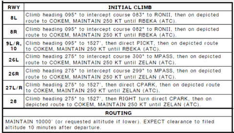 |
| COKEM SEVEN RNAV Departure at KATL Uses "Climb Heading" Legs Image © Jeppessen® - Used by Permission. Not for Navigation. |
While Honeywell knows of no incidents associated with this subject, the difference in ground track versus heading has been noted by the FAA. They have requested that Honeywell remind operators of how the system works. The FAA has reviewed and accepted what Honeywell has documented in this SIL for the purpose of providing awareness to operators.
For more information, please email TalkFMS@Honeywell.com.
Global Customer Committee News
Global Customer Committee (GCC) Continues to Strive Towards Industry Improvements
|
As the GCC looks forward into 2014, the committee also pauses for a moment to reflect upon their mission and strategy. The core mission of the GCC for Honeywell is to listen to the strategic Voice of the Customer (VOC) and act on opportunities to improve products and services. The GCC advises Honeywell on opportunities and top priorities concerning aircraft maintenance, equipment and flight operations relative to business aviation fleets. |
|
|
This customer collaboration drives improvements while holding safety of flight at the highest level. These efforts are facilitated through face to face and virtual interactions across the globe, in which free flowing dialog is highly encouraged among members and Honeywell support staff.
Avionics, mechanical and customer support processes are topics that have been at the forefront of the GCC since inception in 2009. Honeywell is dedicated to bringing flight operations-based issues to the same level of attention. The linkage between the Flight Operations Subcommittee in the Americas and the broader GCC charter has proven to be a powerful partnership that Honeywell wants to replicate across the globe.
Concerted efforts are focused on providing the same beneficial environment for pilots in the Europe and Asia Pacific regions that customers experience in the Americas. As part of this evolution, the GCC is also concentrating on the design and development of a Honeywell pilot-centric website and mobile destination which should be completed mid-2014. In addition, the Direct Access mobile app was launched in the latter part of 2013 thanks to GCC member input.
The GCC is looking forward to a bright 2014 and the beginning of the face to face meetings starting with the Americas on April 8, 2014 in Phoenix, AZ (Deer Valley). The Americas meeting will be followed by the Europe, Middle East, Africa and India meeting April 29, 2014 in Prague, Czech Republic and Asia Pacific meeting on May 13, 2014 in Hong Kong. A full schedule of GCC meetings can be found on the GCC website.
Events and Training Calendar
2014 Events and Training
Honeywell's Flight Technical Services team travels all over the world to bring pilots the latest information on regulations, new technology, and Honeywell product updates. Through Pilot Breakout Sessions at Honeywell Operators Conferences, one-on-one training, entry into service support, and live webinars, Honeywell pilots are on a mission to keep operators informed.
 |
Note: Dates and locations subject to change.
Most of this year's Operators Conferences include pilot breakout sessions with time for participants to ask questions and connect one-on-one with program pilots. Primary topics will include Mandates and Honeywell Solutions, Future Concepts, Service Information Letters, Global Customer Committee Project Overview, and a Pilots.Honeywell.Com Beta-Test Evaluation and Feedback Session. As always, all operator conferences are completely free.
Service Information Letter Briefing
Gulfstream G650 â€" NEW WINDS AVAIL Scratchpad Message & Loss of Performance Initialization Data
Some G650 operators have reported observing a "NEW WINDS AVAIL" scratchpad message during flight, even though wind data was not requested by the crew. Flight crews have stated the message can appear on the MCDU scratchpad once during each flight leg, and/or every 10 minutes during flight. An "INVALID WIND DATA UPLINK" message eventually appears on the MCDU scratchpad.
The "NEW WINDS AVAIL" scratchpad message is caused by an automatic wind data uplink sent in response to an uplinked flight plan (Figure 1). The data link service provider sends waypoint wind data after the flight plan uplink has been acknowledged by the FMS. The wind uplink is predicated only on acknowledgement of the flight plan uplink and does not require a manual wind request.
After the wind uplink data has been processed by the FMS, the "NEW WINDS AVAIL" scratchpad message will be posted. The message will be reposted every 10 minutes if the wind data is not reviewed by the crew. If the wind data is not reviewed and a flight plan waypoint is sequenced or a flight plan waypoint is deleted, an "INVALID WIND DATA UPLINK" message appears. In this case, the message is an indication that the waypoints in the wind uplink no longer correlate to flight plan waypoints.
To prevent the "NEW WINDS AVAIL" scratchpad message from appearing repeatedly, the crew needs to review the uplinked wind data. The data does not need to be accepted into the flight plan performance calculations. If the crew does not want the wind uplink to be sent automatically after the flight plan uplink is acknowledged, they should contact their data link service provider and request that the automatic uplink be removed.
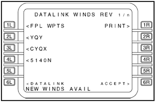 |
| Figure 1 |
Crews have also noted that previously entered performance initialization data is cleared after wind uplink data is accepted into the flight plan performance calculations. When the FMS receives a wind uplink associated with the current flight plan uplink, it calculates flight plan performance using that data. When the calculations are completed, the "NEW WINDS AVAIL" scratchpad message is posted on the MCDU and the crew has the opportunity to accept the wind data.
In order to complete the performance calculations, the FMS creates a copy of the current performance initialization data in the wind subsystem. The current performance initialization data comes from the values entered at the time the flight plan acknowledgement is sent by the FMS. The acknowledgement is sent prior to the crew reviewing or activating the flight plan and is not observable by the crew.
After the wind calculations are completed by the FMS and the "NEW WINDS AVAIL" scratchpad message appears, the crew can elect to accept the wind data. If the wind data is accepted, the FMS will then copy the flight plan created using the wind data and the previously copied performance initialization data to the active flight plan. If the performance initialization had not been completed by the crew before the FMS copied it into the wind subsystem, the performance initialization data will be cleared at this point.
In summary, this issue occurs if the performance initialization data is entered by the crew after sending the flight plan request, and before the winds uplink data is accepted. To prevent the performance initialization data from being cleared upon acceptance of the wind data, the performance initialization data must be entered prior to requesting a flight plan uplink or after the flight plan uplink and corresponding winds have been accepted.
Global Data Center Update
Honeywell Global Data Center â€" FANS and PM-CPDLC Data Link Service Provider
Most operators are familiar with current and upcoming mandates for Future Air Navigation System (FANS 1/A and FANS 1/A+) and Protected Mode Controller Pilot Data Link Communication (PM-CPDLC, otherwise known as ATN-B1 or Link 2000+) certification. In order to comply with these mandates, operators may need approval from their State of registry.
While seeking approval, the required equipment upgrades usually receive the most attention, followed by the application process. It is often during that process when an operator learns they are required to have an approved data link Communication Service Provider (CSP).
The good news is that Honeywell Global Data Center (GDC) data link customers already have an approved CSP. The GDC gives customers access to approved VHF data link networks, including ARINC and SITA, which deliver all Controller Pilot Data Link Communications (CPDLC) and Automated Dependant Surveillance Contract (ADS-C) traffic per standards defined in the ICAO Global Operational Data Link (GOLD) Document.
The GDC also provides customers with Inmarsat's Satellite Communication (SATCOM) FANS capability in remote and oceanic airspace. Aircraft equipped with approved SATCOM systems enable operators to take full advantage of FANS and reduced separation operations in oceanic and other remote regions.
FANS over Iridium Short Burst Data (SBD) will be available to GDC customers in the near future.
Customers may identify Honeywell Global Data Center as their data link service provider on their State of registry application, and GDC Account Services (GDC.Accounts@Honeywell.com) can provide proof of data link service on request.
For more information on FANS, ATN, and other data link topics and mandates, please see this article in the December 2013 issue of Direct-TO, the Honeywell FMS newsletter.
The leader in worldwide data link communications for over 25 years, Honeywell's Global Data Center provides comprehensive flight support services. In addition to proven VHF and satellite data link communications, the GDC provides flight planning, weather, international trip support through their partnership with Jetex, and Flight Sentinelâ„ - an exclusive offering designed to help operators fly more efficiently and avoid hazardous weather and ATC delays. Services can be accessed 24/7 by phone, email, MyGDC.com, and the new MyGDC iPad® app. With flexible package pricing and multiple service plans, GDC services are the right fit for any size flight department.
Honeywell Global Data Center
Toll Free (US & Canada): 1-888-634-3330
International Customers: +1 425-885-8100
Fax: +1 425-885-8930
Email: gfo@mygdc.com
For important GDC updates, weather and airspace information, follow the Global Data Center on Twitter @Honeywell_GDC.
Global Data Center Update
MyGDC iPad App Walkthrough: Electronic Advance Passenger Information System (eAPIS) Filing
With the recent launch of its partnership with Jetex, the Global Data Center (GDC) is rapidly expanding its service offerings for customers operating internationally. Electronic Advance Passenger Information System (eAPIS) filings are one of the many new features being added to the MyGDC iPad App under release 3.0. While eAPIS filings have been available on the full version of the GDC website for many years, customers will now be able to submit manifests using the iPad.
Accessing eAPIS
With the new MyGDC iPad App, users may submit and file an eAPIS (Electronic Advance Passenger Information System) manifest to US Customs and Border Protection for international flights departing or arriving in the US. In order to access this feature, users will need to first open their international flight plan in the Flight Plan menu, which can be accessed from the Dashboard.
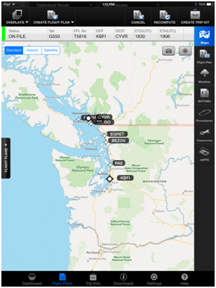 |
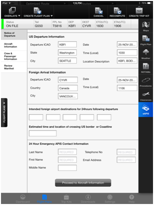 |
Notice of Departure/Arrival
Once the flight plan is open, the eAPIS button will be the bottom icon on the right side of the screen. If possible, it is recommended that customers fill out the eAPIS report after the flight plan has been submitted for filing since the app will automatically populate arrival and departure information. Otherwise, users will need to manually enter departure and arrival information.
Aircraft Information
Once the Notice of Departure / Notice of Arrival page is complete, proceed to the Aircraft Information page. On this page, enter aircraft operator and owner details. Please be aware that the fields change depending on whether a company or individual is selected as the owner or operator.
Crew & Passenger Information
Once Crew & Passenger Information is selected, users will see a list of pilots, crewmembers, and passengers saved under their account. To add a crewmember or passenger who has not previously been saved, tap Add a New Soul near the bottom left corner. Be sure to fill out all applicable fields accurately. Multiple documents can be listed in Document Information, including passports and pilot licenses. Be sure to list passports as Document 1.
To narrow down the list, tap on Pilots, Crews, or Passengers near the top. Above those buttons, there is also a search feature that can quickly find profiles by name. To add someone to the crew/passenger list, tap Select next to the name and then confirm all information is correct prior to adding them to the manifest.
To verify who is included on the crew/passenger list for the current flight, tap on the Crew/Passenger List tab near the right edge of the eAPIS menu. Tapping again on the tab will collapse the list. Once all crew members and passengers have been added, tap on Proceed to Review Manifest.
Review Manifest & Submit
On the Review Manifest menu, carefully check all details on the manifest to ensure accuracy. Once ready to submit, tap on Submit Manifest at the bottom of the page. The GDC will send an e-mail to the address listed under 24 Hour Emergency APIS Contact Information to provide updates on the status of the submission.
The eAPIS filing can also be included in the flight plan's Trip Kit for offline accessibility. Select eAPIS under the Flight Plan Docs section when building a trip kit.
If you require assistance with your eAPIS filing or with any other services, call or email the GDC. Experienced Flight Data Specialists are standing by 24/7/365 to provide support.
Honeywell Global Data Center
Toll Free (US & Canada): 1-888-634-3330
International Customers: +1 425-885-8100
Fax: +1 425-885-8930
Email: gfo@mygdc.com
For important GDC updates, weather and airspace information, follow the Global Data Center on Twitter @Honeywell_GDC.
NavDB Update
INDS Data Manager
|
Jeppesen and Honeywell recently launched INDS Data Manager â€" a new mobile, wireless data loading app for the Primus Apex® integrated flight deck avionics suite. INDS Data Manager simplifies, streamlines, and speeds up the navigation data update process. FAQs for INDS Data Manager Q. What is the INDS Data Manager? Q: How does the INDS Data Manager work? |
|
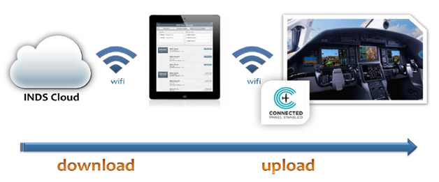
|
|
|
Q: What is significant about the INDS Data Manager? Q: What are the benefits of INDS Data Manager? Q: What are the hardware requirements for the INDS Data Manager? Q: How do I get my PC12 NG configured to work with the INDS Data Mgr? Q: How do customers get the INDS Data Manager app? Q: How do I establish my database services with INDS? |
Global Customer Committee News
GCC Closes Out 2013 with a Strong Drive Setting Up a Bright Outlook for 2014
|
Throughout the year, the Global Customer Committee (GCC) continued to facilitate an environment of customers helping customers improve the business and general aviation industry. At the conclusion of all regional face to face meetings and conference calls, the GCC closed 25 mechanical, 16 electrical, 20 pilot operations and 25 general service items on the Rolling Action Item List (RAIL) totaling an impressive 86 actions. Twenty-five of these RAIL items were part of the global Top 25 list and by closing these, it allowed for new priority issues to be voted into the Top 25. A special thanks to customers who participated on teams to help facilitate this accomplishment and drive a strong finish in 2013. |
|
|
During 2013, the GCC underwent some key leadership changes that proved to be successful, thanks to a robust management operating system. Peter Zeeb was named Chairman for the Americas and conducted his first face to face meeting in September. Peter is working to strengthen the relationship with the eight Original Equipment Manufacturers (OEMs) that Honeywell represents and to improve communication between the customer and the GCC. John Dodson, newly appointed Americas Vice Chair of Communications, is fulfilling a key enabler role for Peter and the GCC along this journey. David Grimm, Americas' prior chairman, provided key leadership and support during this time and the GCC thanks him for his dedication.
Pat Dunn was elected as chairman in the Asia Pacific region and conducted his first face to face meeting in Beijing in November. Pat provided key insights at the meeting and his leadership helped drive a very successful event. Honeywell's GCC process leader, Israel San Pedro, replaced Paco Perez in August and facilitated the global face to face meetings that closed out 2013. Paco has been a key development catalyst for the GCC over the past four years and they wish him the best in his future endeavors.
Leadership transitions for 2014 are underway in the Europe, Middle East, Africa and India (EMEAI) region as we begin to welcome Chairman and Electrical Vice Chair, Antonio Lucchi, Mechanical Vice Chair, Hans Peter Amacher and Communications Vice Chair, Stefano Trevisan. The GCC would like to thank Arnold Leurs for his service as the EMEAI chairman and for his commitment and dedication that helped grow the committee in EMEAI.
The committee is looking forward to 2014 as key initiatives are being driven to enhance customer interactions. Similar to Direct Access, Honeywell's mobile application, pilot oriented website support and mobile applications are high on our priority list. The GCC is also focusing on creating a seamless voice of the customer (VOC) operating system with stronger linkages between the GCC and survey results from Aviation International News (AIN) and Pro Pilot Magazine. Customers helping customers to improve the industry is a critical deliverable of the GCC and Honeywell is looking forward to the continued success of this partnership in 2014 and beyond.
Events and Training
2014 Events and Training Preview
Honeywell's Flight Technical Services team travels all over the world to bring pilots the latest information on regulations, technology, and Honeywell product updates. Through pilot breakout sessions at Honeywell operator conferences, one-on-one training, entry into service support, and live webinars, Honeywell pilots are on a mission to keep operators informed.
This year will be no different. In fact, the number of operator conferences in the Americas region will increase from 13 (plus 15 mini-conferences) in 2013, to 37. Here's a look at the cities Honeywell will be visiting in the Americas this year:
2014 Americas Operator Conference Locations:
| Atlanta, GA - April 10th | Monterrey, Mexico â€" April 10th |
| Belo Horizonte, Brazil â€" March 19th | Morristown, NJ â€" May 13th |
| Birmingham, AL â€" June 26th | New Orleans, LAâ€" June 10th |
| Boise, ID â€" August 19th | Oklahoma City, OK â€" August 20th |
| Burbank, CA â€" May 15th | Omaha, NE - June 19th |
| Calgary, AB â€" June 18th | Panama City, Panama â€" February 14th |
| Canton, OH â€" May 1st | Pittsburgh, PA â€" June 5th |
| Caracas, Venezuela â€" May 14th | Richmond, VA â€" April 29th |
| Carlsbad, CA â€" May 13th | Salt Lake City, UT â€" May 8th |
| Chicago, IL â€" April 3rd | San Jose, CA â€" March 25th |
| Denver, CO â€" May 6th | Sao Paulo, Brazilâ€" August 11th |
| Guadalajara, Mexico â€" April 3rd | Seattle, WA â€" July 22nd |
| Guatemala City, Guatemala â€" February 11th | Toluca, Mexico â€" June 25th |
| Hartford, CT â€" May 15th | Toronto, Canada â€" June 3rd |
| Hillsboro, OR â€" July 24th | Washington DC â€" April 30th |
| Houston, TX (Hobby Airport) â€" September 16th | West Palm Beach, FL â€" February 26th |
| Houston, TX (Intercontinental Airport) â€" September 17th | White Plains, NY â€" May 14th |
| Las Vegas, NV â€" April 29th | |
| Little Rock, AK â€" March 25th | |
| Minneapolis, MN â€" May 29th | |
| Note: Preliminary list. Locations Subject to Change |
Most conferences include pilot breakout sessions with time for participants to ask questions and connect one-on-one with program pilots. Primary topics will include Mandates and Honeywell Solutions, Future Concepts, Service Information Letters, Global Customer Committee Project Overview, and a Pilots.Honeywell.Com Beta-Test Evaluation and Feedback Session.
Keep an eye out for worldwide operator conference dates and locations later this year. Registration information will become available on MyAerospace.com as conference dates approach. As always, all operator conferences are completely free.
Mandate Compliance
Getting Approved for ADS-B
|
As various ADS-B mandates approach, the question about operational approval has become a popular one. The following information is provided to help operators determine if they require formal operational approval (Ops Spec/LOA) and what is required to get an approval. Note that the mandates discussed below are for ADS-B "Out" (i.e. transmitting information from the airplane to a ground station) only. There are currently no mandates for ADS-B "In" (receiving information from ground stations or other aircraft). |
Who Needs an Ops Spec/LOA for ADS-B
|
The answer depends on where the aircraft operates. For example, the FAA is not requiring formal operational approval for ADS-B operations in US airspace. Therefore, operators of US registered aircraft flying solely in US domestic airspace will not require an ops spec or LOA. Likewise, operators of non-US registered aircraft will not require an operational approval from their State of Registry to use ADS-B in US airspace. Australia and Fiji have also said that State of Registry approval is not required, per Australian advisory circular AC 21-45(1) and Fijian aeronautical information circular AIC 04/11. There are however, countries mandating ADS-B and State of Registry approval in their airspace or on specific routes within their airspace. These countries include China, Hong Kong, Singapore, Vietnam, and portions of Canada. As such, FAA authorization (Ops Spec/LOA A353) is available for US operators conducting ADS-B operations outside of US - designated airspace. This is an FAA-issued operational approval that satisfies the requirement in foreign countries. Once received, the Ops Spec/LOA can be used to apply for foreign approval if necessary (e.g. Canadian approval requires submitting this information to meet foreign operator approval). Operators of non-US registered aircraft should check with their regulatory authority for the comparable authorization. |
Applying for ADS-B Operational Approval
|
Required documentation for an Ops Spec/LOA A353 application is listed in FAA Advisory Circular 90-114 (Change 1) Appendix 1. As with most operational approval applications, the operator must submit items including airworthiness approval (AFM statement), MEL requirements, maintenance requirements, operating procedures, and training. Training may be done in-house or through an approved training facility. In-house training must include those items listed in the advisory circular under "Pilot Training. The FAA has published guidance on which countries require operational approval in Information for Operators (InFO) 13009. It also provides links to the ADS-B circulars issued by specific countries. This guidance can be found here: http://www.faa.gov/other_visit/aviation_industry/airline_operators/airline_safety/info/all_infos/ |
Resources and Links to ADS-B information
|
Nav Canada ADS-B Website
http://www.navcanada.ca/EN/products-and-services/Pages/on-board-operational-initiatives-ads-b.aspx Australia ADS-B Websitehttp://www.casa.gov.au/scripts/nc.dll?WCMS:STANDARD::pc=PC_101667 Eurocontrol ADS-B Websitehttp://www.eurocontrol.int/surveillance/cascade FAA ADS-B Websitehttp://www.faa.gov/nextgen/implementation/programs/adsb/ FAA Advisory Circular 90-114, Change 1 â€" ADS-B Operationshttp://www.faa.gov/regulations_policies/advisory_circulars/ FAA Information for Operators (InFO) 13009http://www.faa.gov/other_visit/aviation_industry/airline_operators/airline_safety/info/all_infos/ |
Honeywell is at the forefront of ADS-B technology, offering multiple certified ADS-B equipment solutions. Please click here to request more information.
Global Data Center Update
Global Data Center iPad App Release 3.0
The Global Data Center (GDC) will soon offer Release 3.0 for use by GDC subscribers, offering a wide range of new tools and features. This new release was developed with the help of extensive customer input. New features in Release 3.0 include eAPIS submissions, airport information, enhanced airspace and weather overlays, and increased offline functionality.
Airport Information
With release 3.0, users can select the Search button on the top right corner of the home screen to access airport information. This places useful details, including maximum runway length, operating hours, and approaches, within quick reach. Users can also search for nearby airports and fuel availability. Terminal weather, NOTAMs, and FBO details are also available.
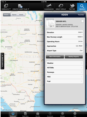 |
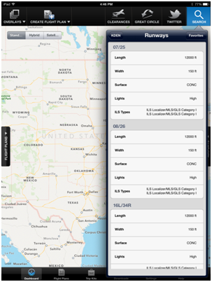 |
Map Overlays
Thanks to the GDC's partnership with WSI, Release 3.0 offers many new weather overlays. These overlays are more detailed than before, with clearer indications of precipitation intensity and wintry precipitation. Multiple overlays can be displayed simultaneously. For example, users can view turbulence overlays while viewing the North Atlantic Tracks.
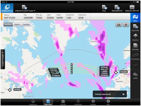 |
eAPIS Filings
Filing an eAPIS manifest can now be done directly from the app. With release 3.0, GDC iPad App users can file and update manifests as they would on MyGDC.com. The eAPIS menu can be accessed from any international flight plan.
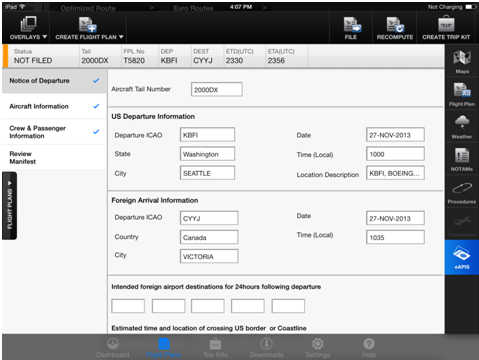 |
Future Releases
Following Release 3.0, the GDC will continue to enhance the iPad App with new features, including new runway analysis and weight and balance tools from APG that are currently available only on MyGDC.com. Also, keep an eye out for a fuel quote tool using data from International Trip Support partner Jetex. Be sure to look for a complete Release 3.0 walkthrough in the January issue of Direct-TO.
Honeywell Global Data Center
Toll Free (US & Canada): 1-888-634-3330
International Customers: +1 425 885-8100
Fax: +1 425-885-8930
Email: gfo@mygdc.com
www.MyGDC.com
For the latest news and updates as well as important weather and airspace information, follow the Global Data Center on Twitter @Honeywell_GDC.
NavDB Update
Important Update for Pilots Operating into Sochi, Russia (URSS)
The Winter Olympics begin February 7th, 2014 in Sochi, Russia (URSS). The ILS approaches at this airport are interesting, in that all are defined with the missed approach point (MAP) prior to the runway:
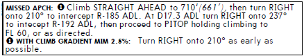 |
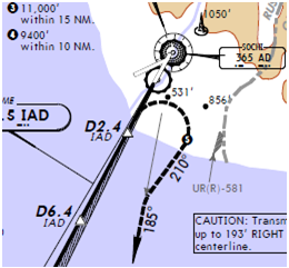 |
(Partial chart image, used with permission of Jeppesen. Not for Navigation.) |
Navigation database coding for an ILS MAP prior to the runway was not permissible in ARINC 424 standards until version 20. As such, Honeywell's Type I Letter of Authorization (LOA) data providers have not been able to provide these approaches to Honeywell and Honeywell has not been able to include these types of approaches in their navigation databases.
Honeywell is pleased to inform operators that the NavDB group is updating their toolset and will be able to process and include these approaches in flight management systems that are capable beginning with the delivery of the cycle 1402 (effective 6 Feb 2014) databases. These ILS approaches will differ from most in that they will not have the runway fix coded on the final approach segment. Instead, a waypoint will be calculated on the glide slope using the highest Decision Altitude (DA) for Category D aircraft.
Realizing this cuts it very close to the beginning of the Olympics, and that every database includes two cycles of data, the 1402 databases will include these approaches in both the cycle 1401 and 1402 data. The delivery cut-off date for cycle 1402 is 29 January 2014, but realistically, the databases generally start to become available for download on the weekend prior, the 24th-26th of January. These ILS approaches will be available to pilots immediately upon loading the 1402 datbase. This will provide these approaches up to two weeks, but no less than one week prior to the start of the Olympics.
Honeywell has been working diligently with data suppliers to ensure this schedule is met and wishes to thank everyone involved in making this enhancement possible. Please send your questions to aviationservices@honeywell.com. Enjoy the games!
NavDB Update
Primus Elite Preprocessed Database
INDS Primus Elite customers now have the option of receiving preprocessed red (NavDB) and blue (Charts) appended databases identified as ELP. The database is available every 14 days for Primus Elite aircraft equipped with the DL-1000 data loader. JSUM users are currently not eligible for the preprocessed database.
With this option, customers no longer need to run the Honeywell Primus Elite Load Preprocessor tool (P/N TM 7038753-001) after receiving the database. Customers already getting CDs delivered now have the option to request the ELP database delivered on a USB stick. For customers using web download, there will only be a single file to download. Either way, customers will receive a database that can readily be loaded using the DL-1000 data loader.
To receive the preprocessed database either by USB or web download, please contact INDS Accounts:
Within the U.S.: 1-888-309-7555 Option 1
International: 303-328-6948 Option 1
Eastern Hemisphere: 0044 (0) 1293 842409 Option1
Email: AccountServices@epicinds.com
Direct Access
|
Honeywell Unveils New Customer Mobile App It just got a lot easier for corporate aircraft pilots and flight departments to get in touch with Honeywell. Honeywell has introduced a new free app for iOS and Android devices called Direct Access: Business Aviation. True to its name, the app utilizes GPS data to provide direct access to Honeywell's nearest tech support staff, dealers, service centers, aircraft on ground support and other vital Honeywell customer resources. |
 |
Direct Access makes it easier than ever for customers to reach out and find someone who can help them, with just a few touches on their smart phone or tablet. It also gives Honeywell the ability to respond to their customers' needs and solve problems quicker and more efficiently.
The new mobile app is designed with extensive input from the Global Customer Committee, who acted as beta testers at every step in the process to ensure that the app meets the real needs of Honeywell's customers. Find out more about what customers have to say in this video.
The intuitive app can be used on iOS and Android devices and can be downloaded for free at the Apple App and Google Play stores.
Honeywell Go Direct™ Briefing
FANS, PM-CPDLC, ADS, and Associated Acronyms
There is a lot of activity in the business jet community around datalink. While there are many features associated with receiving digital information in the cockpit, this article discusses two data intensive capabilities: FANS and PM-CPDLC. They are quite similar in capability, but quite different in their application and how they perform in the cockpit.
Future Air Navigation System (FANS)
FANS has been available to airlines for around 20 years, but is only recently being seen in long range business jets. FANS was released as FANS-1 by Boeing and FANS-A by Airbus. Today, it is commonly referred to as FANS-1/A.
FANS-1/A is used for oceanic and remote operations. The VHF and HF voice communications are replaced by a data link: Controller Pilot Data Link Communication, or CPDLC. CPDLC provides textual communications between the flight crew and the controller, removing the need for voice communications. This improvement eliminates noisy High Frequency (HF) communications between the aircraft and the ground.
Along with CPDLC, FANS-1/A includes surveillance in the form of ADS-C (Automatic Dependant Surveillance â€" Contract). ADS-C allows the ground controller to monitor the aircraft's position, speed, altitude, and other flight parameters via a data link between the aircraft and the ground.
Many pilots view ADS-B and ADS-C as similar technologies, but the two types of surveillance are very different in their application. The ‘B' stands for Broadcast, while the ‘C' stands for Contract. ADS-B communicates to ground stations through the aircraft's transponder, while ADS-C communicates via datalink, either VHF or Satellite. ADS-B broadcasts to all receivers all the time, while ADS-C signals are only received by a facility that has created a contract with the aircraft.
Comparison of ADS-C to ADS-B
| Item | ADS-C | ADS-B |
| Area of Operation | Oceanic/Remote | Domestic Continental |
| Communications | ACARS â€" VHF or Satellite | 1090ES Transponder |
| Equipment | FMS, CMU, Satellite | Transponder, FMS, GNSS |
| LOA required | Yes | Country Dependant |
PM-CPDLC (Link 2000+)
Protected Mode Controller Pilot Data Link Communications (PM-CPDLC) is similar to FANS in that air traffic control and flight crews communicate via textual communications. PM-CPDLC uses the Aeronautical Telecommunications Network (ATN), a system that is much faster than ACARS with stricter message integrity requirements.
Comparison FANS-1/A to PM-CPDLC
| Item | ADS-C | ADS-B |
| Area of Operation | Oceanic/Remote | Europe first â€" Above FL 285 |
| Communications | ACARS â€" VHF or Satellite | ATN VHF â€" VDL/Mode2 |
| Equipment | FMS, CMU, Satellite | FMS, VDL/Mode2 |
| LOA required | Yes | Yes |
PM-CPDLC will be required in Europe for flights above flight level 285 starting in 2015. PM-CPDLC uses an updated VHF data radio technique (VDL Mode 2) to enable fast transmission and reliability in congested airspace, where message delivery delays are far less acceptable. Other countries may adopt PM-CPDLC as an air traffic control mechanism, but the near term plans are for Europe only. There are several exclusions to the mandate, including if an operator is FANS-1/A approved. Dates and details can be found in this presentation.
Looking for assistance with CPDLC approval? Contact Jim Johnson with Go Direct™ to learn how Honeywell can help.
Events and Training
2014 Events and Training Preview
Honeywell's Flight Technical Services team travels all over the world to bring pilots the latest information on regulations, technology, and Honeywell product updates. Through pilot breakout sessions at Honeywell operator conferences, one-on-one training, entry into service support, and live webinars, Honeywell pilots are on a mission to keep operators informed.
Next year will be no different. In fact, the number of operator conferences in the Americas region will increase from 13 (plus 15 mini-conferences) in 2013, to 36. Here's a look at the cities Honeywell will be visiting in 2014:
2014 Americas Operator Conference Locations:
| Atlanta, GA | Monterrey, Mexico |
| Belo Horizonte, Brazil | Morristown, NJ |
| Birmingham, AL | New Orleans, LA |
| Boise, ID | Oklahoma City, OK |
| Burbank, CA | Omaha, NE |
| Calgary, AB | Panama City, Panama |
| Canton, OH | Pittsburgh, PA |
| Caracas, Venezuela | Richmond, VA |
| Carlsbad, CA | Salt Lake City, UT |
| Chicago, IL | San Jose, CA |
| Denver, CO | Sao Paulo, Brazil |
| Guadalajara, Mexico | Seattle, WA |
| Guatemala City, Guatemala | Toluca, Mexico |
| Hartford, CT | Toronto, Canada |
| Hillsboro, OR | Washington DC |
| Houston, TX (Hobby Airport) | West Palm Beach, FL |
| Houston, TX (Intercontinental Airport) | White Plains, NY |
| Las Vegas, NV | |
| Little Rock, AK | |
| Minneapolis, MN | |
| Note: Preliminary list. Locations Subject to Change |
Most conferences include pilot breakout sessions with time for participants to ask questions and connect one-on-one with program pilots. Primary topics will include Mandates and Honeywell Solutions, Future Concepts, Service Information Letters, Global Customer Committee Project Overview, and a Pilots.Honeywell.Com Beta-Test Evaluation and Feedback Session.
Keep an eye out for conference dates and more details after the first of the year. As always, all operator conferences are completely free.
Honeywell Flight Technical Services Q&A
LPV Approach as a Visual Approach Backup
 |
Honeywell Flight Technical Services has received several questions regarding the use of an LPV approach as a backup to a visual approach. Many pilots are familiar with using a localizer and glideslope as a backup when flying a visual approach, but does loading an LPV approach work just as well? Having course guidance and a vertical path helps to maintain a stabilized approach. However, using an LPV to backup a visual approach does have its limitations. For example, if a turn onto final occurs inside the FAF, or a side step to another runway is required, the excessive deviation monitor may remove information from the display. |
Pilots are aware that the ILS transmitter is located physically on the field and projects a signal that is then directly received by the aircraft. With an LPV approach, the FMS navigation database contains the final approach segment (FAS) data block associated with the LPV minimums for the RNAV procedure. The FAS data block consists of the lateral and vertical definition for the final approach path to be flown during the approach. The FAS data block is transmitted from the FMS to the Global Navigation System Sensor Unit (GNSSU) and is used to compute the aircraft lateral and vertical deviations for the final approach segment.
As mentioned previously, there is a monitoring system in the GNSSU for excessive deviations. This monitor is set to trip when either lateral or vertical deviation exceeds two dots of deviation when inside the FAF. The system supplies the pilot with an annunciator in the event of an excessive deviation from the defined LPV final approach segment. This annunciator may be displayed as a flashing lateral or vertical deviation scale in aircraft equipped with an integrated LPV PFD solution, or for aircraft with an external annunciator, an LPV UNAVAIL annunciator is lit and the lateral and vertical deviations are flagged invalid. The annunciator for excessive deviation occurs when the aircraft position has exceeded a set deviation limit (one or two dots of lateral or vertical deviation, depending on the aircraft) while the aircraft is inbound to the runway. The excessive deviation detection initiates 2 NM prior to the FAF and is active until reaching the MAP.
If an RNAV approach with LPV minimums is selected as a backup to a visual approach, be familiar with the excessive deviation logic found in the AFM. If expected to fly direct to, turn final inside the FAF, or possibly side step and exceed two dots lateral deviation, it is recommended that LNAV or LNAV/VNAV minimums is selected from the approach page on the CDU. This will eliminate the possibility of a loss of any advisory information.
Smart Runway® / Smart Landing®
Honeywell Introduces Smart Runway® / Smart Landing® Software
Honeywell defines a runway incursion as any instance on a runway involving an aircraft, vehicle, person, or object that creates a collision hazard or results in the loss of a minimum safe distance between aircraft and other objects on the runway surface. Honeywell defines a runway excursion as an instance where an aircraft exits from the runway at the side or the end of the runway. It could be the result of a technical issue, or an aircraft using a runway that is shorter than required for takeoff or landing.
Regardless, runway incursions and excursions continue to occur for a variety of reasons including poor visibility, poor lighting, bad weather, inadequate paint lines, confusing signs, or any combination of these. As a result, Honeywell has introduced new software for its Enhanced Ground Proximity Warning System (EGPWS), which is already installed on more than 30,000 airline and business aviation aircraft worldwide.It is designed to help break the chain of events that can lead to a runway incursion or excursion by providing aural and visual alerts when the aircraft has not met required safety criteria.
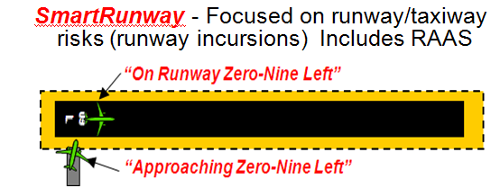
Smart Runway® addresses one of the National Transportation Safety Board's top ten global safety concerns â€" runway incursions. The software is the next generation upgrade to Honeywell's RAAS. It includes the existing advisories offered with the RAAS technology, plus two new advisories for Takeoff Flaps and Taxiway Landing. Using GPS information in conjunction with the EGPWS database, system known airport and runway data, and aircraft position, Smart Runway® knows the runway position, aircraft position, speed, altitude, and heading. It then uses that data to issue up to thirteen advisories to the crew about their environment in relation to the runway. These advisories include what runway the aircraft is currently on, what runway the aircraft is approaching on the ground or in the air, short runways, distance remaining, and taxiway takeoff or landing, just to name a few. All advisories are optional, so operators can tailor the system to suit their needs. The volume levels may also be adjusted at install to suit the individual operator. Positioned for growth, Smart Runway® will also use ADS-B data in the future.
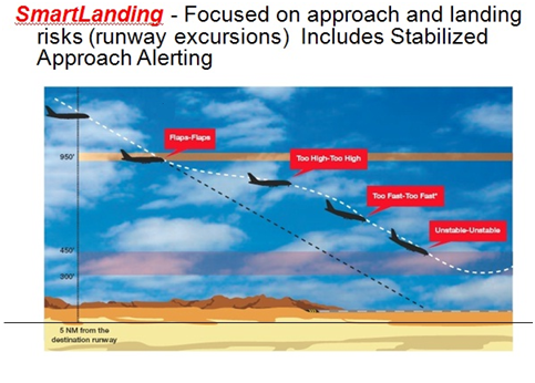
Smart Landing® is a Stable Approach Monitor. It helps reduce the risk of runway excursions by alerting crew members during the landing approach if they are going too fast, if they are too high, or if they are outside the parameters of their landing profile. Smart Landing® complements the operator's Standard Operating Procedures and Flight Operations Quality Assurance programs to improve safety by ensuring compliance with the following stabilized approach criteria:
- Aircraft should be stable at 1000 feet above the airport
- Aircraft must be stable at 500 feet above the airport
- Aircraft is properly configured to land
- Aircraft is on the correct vertical path
- Aircraft is at the correct speed
Visit the Smart Runway® and Smart Landing® website for more information.
Smart Runway ® / Smart Landing®
Temperature Compensation
When should a pilot use temperature compensation? This was a hot subject (no pun intended) brought up during this year's Honeywell Operator Conference pilot break-out sessions. It's best to start by answering a related question: why is temperature compensation needed?
When temperatures are warmer than International Standard Atmosphere (ISA), the true altitude is higher than indicated altitude. The opposite is true if the temperature is colder than ISA; true altitude is lower than indicated altitude. Many pilots will recall the saying, "Hot to cold, look out below." During conditions of colder than ISA operations, there is concern that the aircraft may not maintain adequate obstacle and terrain clearance. Therefore, crews must compensate for published altitudes to correct for non-standard temperatures.
Today, a large number of Honeywell's Flight Management Systems (FMS) offer temperature-compensation to
reduce pilot workload. Using the TEMP COMP function, the FMS provides temperature compensated
altitude constraints which can be applied to the active flight plan.
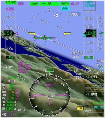
Honeywell Primus Epic PFD Showing Static Air Temperature and ISA
Now back to the original question: when should a pilot use temperature compensation? According to the FAA Instrument Flying Handbook: "Pilots may wish to increase their minimum terrain clearance altitudes with a corresponding increase in ceiling from the normal minimum when flying in extreme cold temperature conditions." It also states, "If compensation is applied by the FMS or manually, ATC must be informed that the aircraft is not flying the assigned altitude." (FAA-8083-15B pg. 5-5)
Transport Canada guidance in the Aeronautical Information Manual states:
"With respect to altitude corrections, the following procedures apply:
- IFR assigned altitudes may be either accepted or refused. Refusal in this case is based upon the pilot's assessment of temperature effect on obstacle clearance.
- IFR assigned altitudes accepted by a pilot should not be adjusted to compensate for cold temperatures, i.e., if a pilot accepts "maintain 3000", an altitude correction should not be applied to 3,000 ft.
- Radar vectoring altitudes assigned by ATC are temperature compensated and require no corrective action by pilots.
- When altitude corrections are applied to a published final approach fix (FAF) crossing altitude, procedure turn or missed approach altitude, pilots should advise ATC how much of a correction is to be applied."
- (Transport Canada, Aeronautical Information Manual, TP 14371E (2013-2). Pg. 281)
Views on temperature compensation vary from country to country, so every operator should look for regulations applicable to their flight. Additional guidance may be available on individual approach procedures.
This article is for familiarization purposes only. Operators are encouraged consult the appropriate regulations, operating procedures, and their Approved Flight Manual before using temperature compensation.
Global Data Center Update
GDC Services for Pilatus Operators
The Global Data Center (GDC) has launched its new Pilatus Flight Support Services for Pilatus operators. Customers can utilize a full suite of flight support tools tailored to the needs of Pilatus operators on MyGDC.com, and within the MyGDC iPad app. Additionally, subscribers have 24/7 access to industry leading support from experienced Flight Data Specialists at the GDC. This special package is available for Pilatus operators at $1,299 per year, per aircraft.
Web-Based Flight Planning with 24-hour Support
The GDC's Pilatus Flight Support Services features worldwide flight planning on a web-based platform. The GDC flight planning engine offers customers several routing options, including wind and temperature optimized routes. These routes take weather into account and generate efficient routes, saving operators time and money. In addition to optimized routes, the GDC also offers recently and frequently cleared routes as well as ATC preferred routes. Customers can also save custom routes for future use.
MyGDC App with Wireless Flight Plan Uplink
The MyGDC App is available for free to all GDC subscribers and allows many of the website's tools to be used on an iPad. Customers can also generate flight plans on the MyGDC App and upload them to the PC-12NG's Primus Apex flight deck, using the Aspen Avionics Connected Panel. This advanced system connects to the iPad over a wireless connection, making it possible to upload flight plans from the MyGDC App quickly and easily. Other apps have been rolled out to allow for wireless data transfer, such as the INDS Data Manager app that can upload charts, navigation, and terrain databases. In addition, the MyCMC App downloads condition monitoring data onto the iPad, and Honeywell MyFlightPath provides moving map data while in flight.
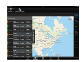 |
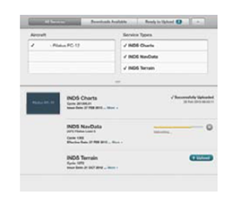 |
| MyGDC App | INDS Data Manager App |
MyGDC Website Tools
The GDC website also offers a wide range of flight planning tools including runway analysis and risk assessment tools, airport data, ATC notifications, pre-departure clearances (PDC) via e-mail, RAIM predictions, airport reservations, eAPIS submissions, and custom flight plan formats. A wide range of text and graphical weather products are available, including weather charts, terminal weather, and passenger weather briefings.
The learn more about how the GDC's Pilatus Flight Support Services will benefit Pilatus operators, contact the GDC:
Honeywell Global Data Center
Toll Free (US & Canada): 1-888-634-3330
International Customers: +1 425 885-8100
Fax: +1 425-885-8930
Email: gfo@mygdc.com
www.MyGDC.com
For the latest news and updates as well as important weather and airspace information,
follow the Global Data Center on Twitter
@Honeywell_GDC
Global Customer Committee News
Face to Face Meeting Update
The fall GCC face to face meetings continue to gain momentum across each region. The Europe, Middle East, Africa, and India (EMEAI) meeting held in Prague, Czech Republic on October 9-10, saw a significant increase in attendance. Guests who came in addition to the GCC member base equaled even stronger customer representation. |
The focus on obtaining the appropriate blend of regional and OEM experience from meeting attendees is critical to the GCC's ongoing drive for excellence. The expansion of Electrical and Mechanical Vice Chair positions into EMEAI is well underway with future actions already being planned for Communication Vice Chair coverage.
As the GCC continues along their journey to solidify and mature membership across all regions, they would like to thank Antonio Lucchi and Hans-Peter Amacher for facilitating key roles during the breakout sessions and throughout the meeting. Their efforts have helped to prove concept of design in adding the Vice Chair positions across all regions, and that the GCC is on the right track towards long term structure.
Events and Training
2013 Calendar of Events and Training Opportunities
Honeywell Customer and Product Support pilots will be available at many events next year, including Honeywell Operators Conferences, online Webinars, and customer/industry events. All Honeywell events are free of charge and everyone is welcome to attend. Pilot breakout sessions and training webinars (eBroadcast sessions) are primarily for pilots, but maintenance personnel and technicians are encouraged to participate as operational tips, current issues, and new products and upgrades are covered. Instructors are Honeywell training pilots with thousands of hours of experience who are type-rated on various platforms including Gulfstream, Dassault, Bombardier, Cessna, Beechcraft, Pilatus, and Embraer.
| Title | Location | Date |
| Global Customer Committee Americas Teleconference | Online | 12/10/2013 |
| Global Customer Committee EMEAI Teleconference | Online | 12/11/2013 |
| Global Customer Committee APAC Teleconference | Online | 12/12/2013 |
| 2014 Operators Conferences and Training Events | Online | Coming Soon |
Note: Remaining 2013 Operators Conferences do not include pilot breakout sessions.
Schedule and location is subject to change based on registration for each event. Interested in attending a seminar or webinar? Most sessions require advanced registration. Contact Jeff Holt at +1-817-564-3436 or email Jeffrey.Holt@Honeywell.com.For more information on GCC events, visit committees.honeywell.com.
Miss an eBroadcast session? Training is recorded and available any time by clicking here.
Global Customer Committee News
GCC Americas Face 2 Face Recap
| When the Americas Global Customer Committee (GCC) met Sept. 23-25, the group moved forward with prioritizing its Rolling Action Items List (RAIL), heard from Aerospace leadership, and discussed ways to promote Honeywell and the GCC. |
|
| Among speakers kicking off the event was the GCC's newly elected Americas Chairman, Peter Zeeb, Chief of Maintenance for Caesars Entertainment Aviation Services; Tim Beatty, Vice President of Customer and Product Support for Business and General Aviation; and Adrian Paull, Vice President of Aerospace Customer & Product Support. Jon Dodson, newly elected Vice Chair of Communications from Duncan Aviation, also addressed the committee with a call to the GCC for communication action. Jon asked for members to leverage personal testimonials and the strength of each member's experience to promote the work that is being done by Honeywell and the GCC as a whole. | |
At the conclusion of day three, member Stephen Farrell, from Standard Aero, challenged the GCC to be an even stronger entity. Similar to Jon's day one messaging, his call for action focused on being an advocate for the GCC and Honeywell. The resulting 30-minute discussion covered the direction of the GCC, how members can better promote the GCC throughout the industry to increase awareness of the great things Honeywell is doing, and addressing the industry's top concerns.
Specific actions are under way to increase visibility of the committee during industry functions, get news of improvements Honeywell has accomplished out to the business aviation industry, and solicit feedback on these improvements through industry surveys including AIN and ProPilot.
Other highlights of the meeting include:
- Reviewing the RAIL and closing 32 items on the list, in addition to two from the Top 25. Another Top 25 item moved to the follow-up agenda.
- Prioritizing RAIL items to move into the Top 25 queue.
- Working team sessions, which have continued to mature to a new level of productivity. The avionics break-out session provided a prime example of quality discussions fueled by Engineering and Marketing & Product Management (M&PM) engagement. Discussions around mandates and product road maps proved valuable for both GCC and Honeywell during the exchange.
- Presenting Honeywell's support plan for the upcoming Brazil World Cup in 2014, which received very positive feedback. This session gave Honeywell more ideas to further promote its presence in Brazil prior to and during the event, with suggestions added to the current plan as opportunities to explore.
During the leadership debrief, it was unanimously agreed the meeting was highly productive. With breakout sessions evolving into the most effective segment of the meetings, the committee suggested Honeywell increase the number and duration of these sessions. The popularity of the breakout sessions reflects engagement from Honeywell support functions during these face-to-face meetings and demonstrates the effectiveness of knowledgeable and diverse member attendance, which has met or exceeded levels of larger groups, solidifying the strategy of quality over quantity. This approach will continue through Honeywell's ongoing drive to improve.
The Global Customer Committee, an 85-member group that includes pilots and chiefs of maintenance from corporate flight departments, as well as representatives of large aviation service centers that maintain aircraft for smaller operators, was created so that Honeywell could hear directly from customers. In addition to helping Customer & Product Support, and Business & General Aviation teams identify and address customer issues, GCC feedback provides valuable insight to all Aerospace businesses and functions. For more information, please email GCC@honeywell.com. To learn more about becoming a member or submitting an issue to the GCC, please visit the GCC website.
NavDB Update
When is a Special Navigation Database Required?
An aircraft gets an update to the latest service bulletin and is now RNP capable. The question is; does it need an RNP database?
Honeywell gets a version of that question all of the time. A maintenance manager is working through the paperwork of a recent aircraft modification. The aircraft has become RNP certified. A pilot heard there was a different database required. Emails are sent and voice messages are left. Here's the full story on RNP and navigation databases.
Required Navigation Performance (RNP) has several different accuracies. Each one is meant for different flight requirements. Here are some of the common RNP accuracies:
| RNP Accuracy | Description | Special Database Required? |
| RNP 10 and RNP 4 | Accuracy to 10 NM or 4 NM. This RNP value is stated for oceanic and remote flight operations. | No |
| RNP 2 and RNP 1 | Accuracy to 2 NM or 1 NM. This RNP value is stated for terminal area operations, including SIDS and STARS. B-RNAV and P-RNAV are similar acronyms. | No |
| RNP AR | Authorization Required. This is for approaches with RNP values of 0.1 NM to 0.3 NM. | Yes |
Honeywell creates avionics for many different aircraft types, and therefore creates a large number of navigation databases. Of the above RNP types, only RNP AR requires a unique navigation database. An aircraft needs this database only if it is authorized to fly these specialized approaches.
Why is there a separate database for RNP AR? Because of the unique nature of RNP AR procedures and the special database validation processes required, Honeywell has created a version of the navigation database that adds approved RNP AR approaches while keeping a separate version without them. This was done to reduce confusion and prevent operators from inadvertently flying an RNP AR approach without the proper approval..
As an FAA authorized RNP AR consultant, the GoDirect team can answer additional questions about RNP AR. Whether it's related to navigation databases, operational approval, or approach monitoring, they cover it all. Interested in getting certified for RNP AR operations? Honeywell's GoDirect team is standing by to make the process simple and straightforward. Please contact RNP@Honeywell.com.
Flight Management System (FMS) Software Version 6.1 Upgrade Corner
Aircraft Certification Update
FMS Software Version 6.1, and the many new features and enhancements that come with it, is certified for the majority of eligible aircraft. The final remaining certifications are expected by the end of Q1, 2014.
The certification status list below is current as of October, 2013
| Aircraft Type | Part Number | Certification Status |
| Bombardier Challenger 601 | 7018879-03034 | Certified: 08/03/10 |
| Bombardier Challenger 601 | 7018879-03040 | Certification Target: Q1 2014 |
| Bombardier Global Express | 7017300-6X010 | Certified: 12/17/12 |
| Cessna Citation X | 7017300-31554 | Certification Target: Q4 2013 |
| Dassault Falcon 900B | 7018879-03034 | Certified: 12/17/10 |
| Dassault Falcon 900B | 7018879-03040 | Certified: 08/20/13 |
| Dassault Falcon 900C | 7017300-4XX25 | Certification Target: Q1 2014 |
| Dassault Falcon 900EX | 7017300-4XX25 | Certified: 09/09/13 |
| Gulfstream GIV | 7018879-03036A | Certified: 10/30/12 |
| Gulfstream GIV | 7018879-03040 | Certification Target: Q4 2013 |
| Gulfstream GV | 7017300-56026 | Certified: 05/07/13 |
| Hawker 800 | 7018879-03034 | Certified: 05/20/11 |
| Hawker 800 | 7018879-03040 | Certification Target: Q4 2013 |
| Embraer Legacy 600 | 7018879-03038 | Certified: 02/08/13 |
Aircraft Certification Dates
FMS Software Version 6.1 enhancements and new features include WAAS-LPV approaches, VNAV temperature compensation, circling approaches, en route holding patterns, and more. Operators are encouraged to contact their nearest Honeywell Area Sales Manager for more information about upgrading to FMS Software Version 6.1.
Global Data Center Update
GDC Tips and Tricks:iPad App
The MyGDC App makes it easy to generate and file flight plans using the iPad. Customers with wireless data access or a Wi-Fi connection can use the App to obtain real-time data on flight plans and ATC filings, along with text and graphical weather.
Downloading the MyGDC App
The App is available for download in the Apple App Store as "Honeywell MyGDC" and is fully compatible with iOS 7. While the App is free of charge, a GDC ID and password are required to use the App.
Generating a Flight Plan
Begin by selecting Create Flight Plan near the top of the screen. A drop down menu with flight plan parameters will appear. Aircraft, Departure, Destination, and ETD fields are required while others are optional. Tap on each field to make entrie
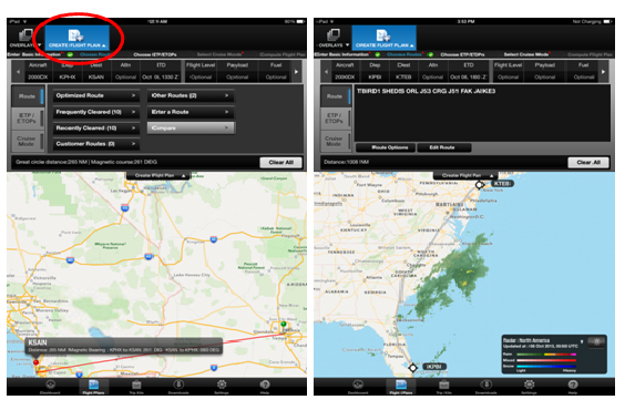
Create Flight Plan Drop Down Menu
To assist with planning, graphical weather overlays can be viewed while choosing routes. Customers subscribing to the GDC's new Premium Graphical Weather can view NEXRAD overlays for Europe and Australia along with equatorial SATRAD overlays
Reviewing Flight Plans
Flight plans that were created using the App, over the phone, or on MyGDC.com can be reviewed from the Review Flight Plans list. Select the Flight Plans tab from the dashboard page on the left edge of the screen. Select the desired flight plan from the list that appears.
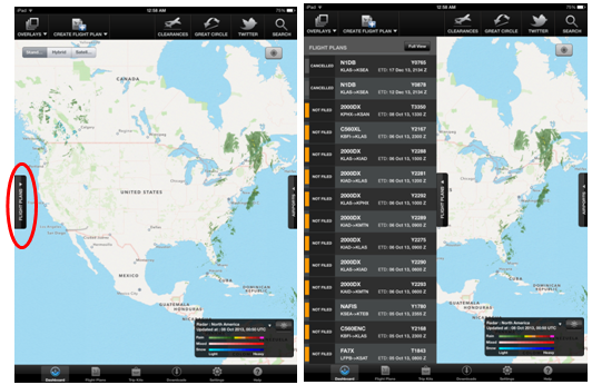
Review Flight Plans List
Once the flight plan has been selected, it can be filed with ATC, viewed as it was last computed, or used to check weather, NOTAMs, airport diagrams, and approach plates.
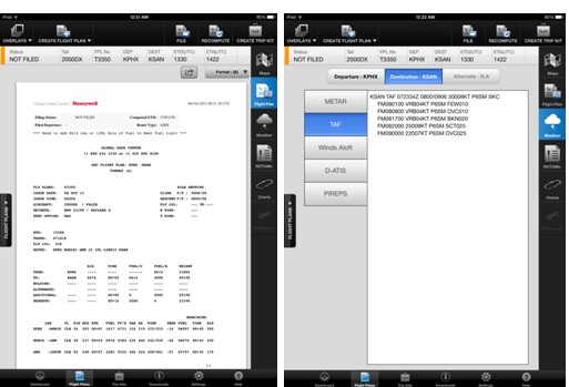
Re-Computing Flight Plans
Using the iPad App to re-compute flight plans with the latest data is quick and easy. As with the re-compute function on the full MyGDC website, subscribers can change cruise modes, flight levels, alternates, departure times, and check for updated fuel burns and enroute times. To get started,click the ReCompute button near the top right corner of the screen when viewing any flight plan.
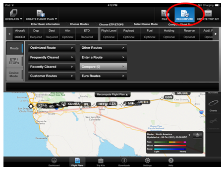
Check the GDC Update section of Direct-TO every month for more on how to make the most of the MyGDC App. For additional questions regarding the iPad App, please contact the GDC. Flight Data Specialists are standing by 24/7 to assist over the phone, via e-mail, datalink, and Live Chat.
Honeywell Global Data Center
Toll Free (US & Canada): 1-888-634-3330
International Customers: +1 425 885-8100
Fax: +1 425-885-8930
Email: gfo@mygdc.com
www.MyGDC.com
For the latest news and updates as well as important weather and airspace information, follow
the Global Data Center on Twitter @Honeywell_GDC.
Honeywell GoDirect Briefing
RNAV Approach Procedure Naming Conventions â€" A Refresher
GPS-based approach procedures are constantly being developed, adding accessibility and flexibility for operators. Additionally, regulatory authorities are publishing multiple RNAV approach procedures to a single runway end. This allows for differences in missed approaches, transitions, aircraft performance (missed approach climb gradients), and navigation equipment/performance (SBAS/LPV, RNP, RNP AR). The following is a description of charting conventions and characteristics for cases like this, so that pilots may better identify the approach type and what is required to fly it.
Distinguishing Different Types and Requirements
There are two types of RNAV procedures, shown below and belonging to a hypothetical Runway 22:- RNAV (GPS) Rwy 22
- RNAV (RNP) Rwy 22
1.RNAV (GPS) may also be charted as RNAV (GNSS) outside the US.
2.RNAV (RNP) procedures are RNP AR (or SAAAR) and require an LOA/Ops Specs for all operators
In the US, if multiple RNAV procedures exist for the same runway end, an alphabetic suffix will be included in the approach name. This alphabetic suffix will also be included in an approach clearance:
RNAV (RNP) Z Rwy 22
RNAV (GPS) Y Rwy 22
RNAV (GPS) W Rwy 22
Note: Other countries may use different suffixes such as numbers or the phonetic alphabet to distinguish different RNAV procedures from one another.
Loading the Correct Procedure
Most FMS (with latest software upgrades) are capable of displaying multiple RNAV procedures to the same runway. They are differentiated by the alphabetic suffix as in the examples below:
- RNAV-X
- RNAV-Y
Be aware that an RNAV procedure in the database may be either an RNAV (GPS) or RNAV (RNP) approach. The only way to differentiate/confirm is by the alphabetic suffix.
For those FMS that cannot display multiple RNAV procedures, Jeppesen will include the procedure that most customers are capable of flying. See the Jeppesen Briefing Bulletin titled "Multiple Approach Procedure Indicators" for specific information on procedure selection for FMS that are limited to one RNAV approach per runway.
Interested in getting certified for RNP AR operations? Honeywell's GoDirect team is standing by to make the process simple and straightforward. Please contact RNP@Honeywell.com.
Events and Training
2013 Calendar of Events and Training Opportunities
Honeywell Customer and Product Support pilots will be available at many events this year, including Honeywell Operators Conferences, online Webinars, and customer/industry events. All Honeywell events are free of charge and everyone is welcome to attend. Pilot breakout sessions and training webinars (eBroadcast sessions) are primarily for pilots, but maintenance personnel and technicians are encouraged to participate as operational tips, current issues, and new products and upgrades are covered. Instructors are Honeywell training pilots with thousands of hours of experience who are type-rated on various platforms including Gulfstream, Dassault, Bombardier, Cessna, Beechcraft, Pilatus, and Embraer.
| Title | Location | Date |
| Honeywell Operators Conference | Beirut, Lebanon | 10/21/2013 |
| NBAA 2013 â€" Booth N4100 (More Info) | Las Vegas, NV | 10/22 â€" 10/24/2013 |
| Honeywell M&O Sessions at NBAA 2013 (Schedule) | Las Vegas, NV | 10/22/2013 |
| Global Customer Committee APAC Face 2 Face | Beijing, China | 11/11 â€" 11/12/2013 |
| Honeywell Operators Conference | Jakarta, Indonesia | 11/14/2013 |
| Global Customer Committee Americas Teleconference | Online | 12/10/2013 |
| Global Customer Committee EMEAI Teleconference | Online | 12/11/2013 |
| Global Customer Committee APAC Teleconference | Online | 12/12/2013 |
| 2014 Operators Conferences and Training Events | Worldwide | Coming Soon |
Note: Remaining 2013 Operators Conferences do not include pilot breakout sessions.
Schedule and location is subject to change based on registration for each event. Interested in attending a seminar or webinar? Most sessions require advanced registration. Contact Jeff Holt at +1-817-564-3436 or email Jeffrey.Holt@Honeywell.com.For more information on GCC events, visit committees.honeywell.com.
Miss an eBroadcast session? Training is recorded and available any time by clicking here.
RNP AR Charting
The Mystery RNP Value at the IAF
RNAV (RNP) approaches, also referred to as RNP AR (Authorization Required) approaches, have a number of specific charting characteristics. One of these is the RNP value that's charted at the initial approach fix (IAF) of some RNP AR procedures. There has been a lot of confusion about these values, what they represent, and how an operator should use them.

Example: KMSO RNAV (RNP) Rwy 29 approach
Shown above is the plan view for the RNAV (RNP) Rwy 29 for KMSO (Missoula, MT). Note the RNP values of 0.5 published at the feeder fixes WEDAK and PIXXI, and the IAF, MSO.
What's the significance of the RNP value charted at the IAF or feeder fix?
When the FAA designs an RNAV (RNP) approach, they attempt to use "standard" RNP values: RNP 2.0 for feeder routes and 1.0 for initial and/or intermediate segments. If terrain or airspace constraints prevent that, they will use lower values and note the lowest value used adjacent to the feeder or initial approach fix. Therefore, an RNP value published at the feeder fix or IAF simply represents the lowest RNP value required between that waypoint and the final approach fix (FAF).
What should pilots do with the RNP value charted at the IAF?
Nothing, if operating an aircraft equipped with a Honeywell FMS. This RNP value is charted for those operators of flight management systems that require manual input of RNP values by phase-of-flight. Honeywell FMS approved for RNP AR read RNP values directly from the navigation database. (Some earlier software versions require an RNP value in the MANUAL field of the FMS RNP page.)
In summary, the RNP values charted at feeder fixes or initial approach fixes are there as part of the FAA charting convention for RNP AR procedures. They are charted simply to make the flight crew aware that RNP value(s) less than the "standard" were used between the feeder/IAF and the final approach fix.
iPads in the Cockpit
Using the iPad as an EFB


Business Aviation has shown significant interest in the iPad (and other tablet devices) for document management, chart management, and navigation reference. Applications (Apps) are turning the iPad into an Electronic Flight Bag (EFB) and EFBs are creating opportunities for unprecedented operational efficiency. One of the questions posed most frequently to the Flight Technical Services team is, "what are the different classes and types as they pertain to the iPad and what does that mean to the aircraft operator?"
The iPad falls into the Class 1, Type A/B categories which are described in FAA AC 120-76A, Guidelines for the Certification, Airworthiness, and Operational Approval of Electronic Flight Bag Computing Devices. AC 120-76A outlines an acceptable method of compliance for the certification, airworthiness, and operational approval of both portable and installed EFB aircraft computing devices.
Hardware classes are defined in three classes of EFBs: Class 1, 2, and 3.
Class 1 is the standard commercial-off-the-shelf (COTS) equipment such as laptops or handheld electronic devices. These devices are used as loose equipment and are typically stowed during critical phases of flight. A Class 1 EFB is considered a Portable Electronic Device (PED). Class 1 EFBs can be used to display Type B applications in critical phases of flight provided they are ‘secured and viewable.'
Class 2 is the standard COTS equipment, a PED, connected to an aircraft mounting device during normal operations, and required to go through an administrative control process to add, remove, or use in the aircraft. Note that Class 2 EFB system power, data connectivity, and mounting devices require FAA Aircraft Evaluation Group (AEG) evaluation and certification approval from the FAA Aircraft Certification Service (AIR).
Class 3 is installed equipment that requires FAA AIR approval, except for user modifiable software that may be used to host Type A and B applications. Class 3 EFB system certification requirements enable additional applications and functions.
Software types are defined in three types: Type A, B, and C.
Type A is static applications such as document viewer (PDF, HTML, XML formats). This includes Flight Crew Operating Manuals (FCOMs), Pilot Operating Handbooks (POHs), Airport / Facility Directories (A/FDs), etc. Appendix A of AC 120-76A has a comprehensive list of Type A EFB applications that require Flight Standards District Office (FSDO)/Principal Inspector (PI) approval. Type A software applications do not require AIR approval.
Type B are interactive applications such as electronic approach charts or approach charts that require panning, zooming, and scrolling, performance calculations based on software algorithms, electronic checklists, applications that make use of the Internet and/or other aircraft operational communications (AOC) or company maintenance-specific data links to collect, process, and then disseminate data, etc. Appendix B of AC 120-76A has a comprehensive list of Type B EFB applications that require FSDO/PI approval. Type B software applications do not require AIR approval.
Type C applications include primary flight displays (PFDs). Type C applications require AIR design approval, except for user modifiable software, which may be utilized to host Type A and B applications.
Class 1, Class 2, and Class 3 EFBs can act as a substitute for the paper manuals that pilots are otherwise required to carry with them. While Part 91 Operators (those not flying for hire, including private and corporate operators) can use their Pilot In Command (PIC) authority to approve the use of Class 1 and Class 2 EFBs (which are PEDs), operators with OpSpecs (Part 135, Part 121) must seek operational approval through the OpSpecs process.
PEDs used in a Class 1 or Class 2 configuration must meet the rapid decompression testing requirements. iPad has passed the DO-160F Rapid Decompression test.
Any data connectivity of PEDs used in a Class 1 or Class 2 configuration to aircraft systems and any mounting or attachment of PEDs used in a Class 1 or Class 2 configuration to the aircraft must be performed in accordance with a Supplemental Type Certificate (STC), Type Certificate (TC), or Amended Type Certificate.
The display of own-ship position on the ground must meet the requirements of AC 20-159 (Obtaining Design and Production Approval of Airport Moving Map Display Applications Intended for Electronic Flight Bag Systems) and/or TSO C-165. The display of own-ship position in flight is prohibited on Class 1 or 2 configurations.
FAA regulation 91.21(5) prohibits wireless and cellular electronics in aircraft while taxing and in the air. FAR 91.21 does allow the PIC to allow non-transmitting devices in the aircraft, but only after the PIC tests it under the guidelines of FAA AC 91-21.1b, Use of Portable Electronic Devices Aboard Aircraft.
Procedures should be designed to ensure that the flight crew knows what aircraft system (e.g., Engine Indicating and Crew Alerting System (EICAS), Flight Management System (FMS), or EFB) to use for a given purpose, especially when both the aircraft and EFB systems provide information. Procedures should also be designed to define the actions to be taken when information provided by an EFB does not agree with that from other flight deck sources, or when one EFB disagrees with another. If an EFB generates information that existing cockpit automation also generates, procedures should be developed to identify which information source will be primary, which source will be used for backup information, and under what conditions to use the backup source. Whenever possible and without compromising innovation in design/use, EFB/user interfaces should be consistent (but not necessarily identical) with the flight deck design philosophy.
The operator should have a procedure in place to allow flight crews to confirm the revision numbers and/or dates of EFB flight databases and software installed on their units for each flight. An example of a date-sensitive revision is an aeronautical chart database on a 28-day revision cycle. Procedures should specify what action to take if the applications or databases loaded on the EFB are out-of-date.
EFBs are now mature products that provide a wide range of benefits for business and general aviation cockpits. For each phase of flight (pre-flight, taxi, enroute, approach, landing, and gate) applications cover a considerable amount of data for weight and balance, fuel burn, wind calculation, flight planning, charts, weather, checklists, airport maps, GPS Nav, terrain, pilot log book, data loader, and document viewer. Understanding and implementing the guidelines for the different classes and types as they pertain to the iPad and EFBs permit the aircraft operator to take advantage and make full use of this new technology.
Global Data Center Update
Expanded Graphical Weather Coverage
The GDC now offers enhanced NEXRAD weather radar coverage, with a more detailed image available for a greater coverage area. GDC subscribers can take advantage of radar coverage available for a larger portion of North America including Hawaii, Alaska, and the Caribbean.
Epic Datalink Graphical Weather subscribers can also now view the expanded coverage areas. Additionally, the GDC recently launched Premium Graphical Weather, which provides radar coverage of Europe and Australia on Epic platforms.


Graphical weather on MyGDC.com and the MyGDC iPad App also depicts a more detailed radar image. Images show a much wider range of cell intensities and clearly indicate precipitation mix (such as rain and snow).
These enhancements bring greater value to the GDC's industry-leading graphical weather products, including Epic Datalink Graphical Weather, WINN Weather, and online graphical weather accessible at www.mygdc.com.
Whether being used for flight planning, or while in flight, the GDC's graphical weather products allow flight crews to maintain situational awareness in a variety of weather conditions. For more information on enhanced graphical weather, please contact the GDC.
Honeywell Global Data Center
Toll Free (US & Canada):
1-888-634-3330
International Customers:
+1 425 885-8100
Fax: +1 425-885-8930
Email: gfo@mygdc.com
For the latest news and updates as well as important weather and airspace information, follow the Global Data Center on Twitter @Honeywell_GDC.
Aero Training TV
Online Technical Training Videos
Honeywell Aero Training TV offers a rapidly-expanding library of online technical videos for pilots. Aerospace Training Solutions produces how-to videos on Primus Epic, Primus Elite, Primus Apex, LPV, VGP, and other important topics.
Videos can be viewed on a desktop, tablet PC, notepad, or smart phone. Every video features scrolling transcripts synchronized with playback. The powerful vSearch feature searches the library for specific words or phrases, and then takes pilots to the exact spot in the video where those words are spoken.

Honeywell Flight Technical Services continually produces new videos, and encourages pilots to check-in often. Aero Training TV also offers RSS feeds to pilots, delivering timely notifications of new material.
Click here to explore Aero Training TV.
Flight Management System (FMS) Software Version 6.1 Upgrade Corner
FMS Software Version 6.1 Upgrade Pilot Support
Honeywell's Flight Technical Services team offers Entry Into Service (EIS) support for all FMS 6.1 upgrades. They provide detailed familiarization courses to flight crews, ensuring they're aware of changes included with the upgrade and familiar with how to use its new features. EIS sessions are hosted online so crews can login from wherever they may be.
In addition, Honeywell Flight Technical Services provides ongoing technical and operational support to customer flight departments. The pilot group maintains currency in aircraft operations, and creates and oversees courseware for aircraft and associated products.
Operators who have already upgraded and would like to set-up a familiarization session can contact the Flight Technical Services team at talkfms@honeywell.com. Please include EIS Support in the subject line.
NOTE: Honeywell C&PS Flight Operations is not an FAA-certified provider of pilot training courses.
Honeywell Technical Operations Center
C&PS Simplifies Tech Support Calls with New Direct Phone Numbers
Getting technical support from Honeywell Aerospace just got faster and simpler. As of August, new 24/7 phone numbers take customers directly to the Technical Operations Center (TOC) without having to navigate multiple choices to reach technical support.
Customers in the U.S. can call 855-808-6500, and customers outside the U.S. can call 602-365-6500 for immediate assistance.
Previously, customers used a generic Aerospace call center number that included choices such as spares, maintenance plans and technical publications ahead of the option to connect with technical support. Now the new number allows customers to simply choose Option 1 for avionics or Option 2 for mechanical to start talking to a technical support engineer.

The direct connect number is in response to customer requests and feedback from Customer & Product Support's Global Customer Committee members.
The new direct phone numbers went live Aug. 12. Technical support engineers in Phoenix, Prague and Shanghai staff the TOC to provide Air Transport & Regional, Business & General Aviation and Defense & Space product troubleshooting expertise to customers across the globe.
In addition to calling, customers can continue to reach the TOC through email at aerotechsupport@honeywell.com, or through the aerospace portal at myAerospace.com.
Events and Training
2013 Calendar of Events and Training Opportunities
Honeywell Customer and Product Support pilots will be available at many events this year, including Honeywell Operators Conferences, online Webinars, and customer/industry events. All Honeywell events are free of charge and everyone is welcome to attend. Pilot breakout sessions and training webinars (eBroadcast sessions) are primarily for pilots, but maintenance personnel and technicians are encouraged to participate as operational tips, current issues, and new products and upgrades are covered. Instructors are Honeywell training pilots with thousands of hours of experience who are type-rated on various platforms including Gulfstream, Dassault, Bombardier, Cessna, Beechcraft, Pilatus, and Embraer.
| Title | Location | Date |
| Honeywell Operators Conference | Tokyo, Japan | 10/15/2013 |
| Honeywell Operators Conference | Beirut, Lebanon | 10/21/2013 |
| Honeywell Operators Conference | Jakarta, Indonesia | 11/14/2013 |
| 2014 Operators Conferences and Training Events | Worldwide | Coming Soon |
Note: Remaining 2013 Operators Conferences do not include pilot breakout sessions.
Schedule and location is subject to change based on registration for each event. Interested in attending a seminar or webinar? Most sessions require advanced registration. Contact Jeff Holt at +1-817-564-3436 or email Jeffrey.Holt@Honeywell.com.
Miss an eBroadcast session? Training is recorded and available any time by clicking here.
Direct-TO - NavDB Update
Approaches with Flight Path Angles in Excess of 6.0 degrees Included in Cycle 1308 Database.
Procedures with flight path angles in excess of 6.0 degrees have been restored to applicable Honeywell navigation databases. Inclusion of these procedures is effective with Cycle 1308. Solving the issue that led to procedure removal was a joint effort between Honeywell and their customers, though the Global Customer Committee.
For background on the procedure removals, please review this article from the June edition of Direct-TO.
Direct-TO - Flight Management System Version 6.1 Upgrade Corner
The Honeywell FMZ-2000 Flight Management System (FMS) version 6.1 provides better access to more airports, increased safety, reduced crew workload and significant operational efficiency improvements for operators. In the previous edition, questions regarding applicability, and basic and advanced features were addressed. In this edition, the focus will be on WAAS / LPV.
Wide Area Augmentation System / Localizer Performance with Vertical Guidance (WAAS/LPV)
1. Do I need a new GPS receiver for the WAAS upgrade?
In most cases the answer is yes. If the aircraft has GNSSUs with a part number of HG2021GD02 or earlier, then the GPS receiver must be replaced with a new version - HG2021GD04.
If an aircraft has a GNSSU part number HG2021GD03 then this unit can be sent in for a software upgrade at a considerably lower cost than purchase of a new unit. When providing a quote, the dealer / installer will be able to verify which units are upgradeable and which units need to be replaced.
2. What other hardware do I need to upgrade to WAAS?
The standard GPS antenna must be replaced with an active GPS antenna. The active antennas use the same footprint and hole pattern as the old units. They also used the same coaxial cable so no new wiring needs to be installed.
If the aircraft has NZ-2000 navigation computers and an SPZ-8000 FCS (CL-601-3A/R, F-900B, H-800/XP, etc.) then LPV annunciator lights will need to be installed in the instrument panel. Also, an interface box (Digital Discrete Adapter - DDA) to drive the lights needs to be installed. This configuration is used when installing new WAAS receivers. Please check with the installer or STC holder to verify if annunciator lights and DDA are required.
3. Will WAAS be compatible in other regions of the world?
Yes. WAAS uses a corrective SBAS signal from space. This same frequency / information coding will be used in other SBAS regions thus making the GPS receiver compatible in other parts of the world. Examples of other SBAS regions are EGNOS in Europe, GAGAN in Asia and MSAS in Japan.
4. What is the value of the WAAS upgrade?
The primary reason an operator would upgrade to WAAS is the LPV approach. There were over 3400 published LPV approaches in the US in January, 2013, and the list is growing. These approaches allow near-ILS CAT I minimums at airports with and without an ILS installed.
Other advantages to WAAS GPS (when in the WAAS footprint) include: (1) no predictive RAIM required, (2) compliance with emerging FAA ADS-B requirements (NextGen), (3) precision vertical (GPS altitude) navigation to fly LPV approaches.
FANS 1/A will be the focus of the next edition of FMS 6.1 Upgrade Corner. If you have questions, contact talkfms@honeywell.com. Please include FMS 6.1 Upgrade Corner in the subject line.
Direct-TO - NZ 6.1 Active Leg Preview Function
One of the many new features operators will enjoy with NZ 6.1 software is the “Preview an Active Leg Change in Flight” function. Honeywell has received several reports from newly upgraded operators that the functionality does not work properly, so the intent of this brief is to explain the new function and provide guidance on its use. The figures below are used only to demonstrate how the function works. Please refer to the Honeywell FMS NZ6.1 pilot handbook for additional information.
The preview function allows the crew to display a graphical view of the active flight plan with pending changes to the active waypoint. Once pending changes are displayed on the CD-820, the pilot can accept or reject the change. The aircraft must have CD-820 units installed in order to utilize the preview function. In addition, the CDU may not match the MFD display exactly when using this function. Three key points to remember when previewing pending changes are: the aircraft must be in flight, the crew is previewing a change to the active leg only, and the “DIR” button on the CDU is not used with the preview function.
Please reference the sample flight plan below in figure 1. The following steps summarize the method of previewing the active leg of a flight plan.
First, the pilot down selects a waypoint that is further down in the flight plan to the scratchpad (Fig.2). The pilot can then up select the waypoint as the TO waypoint in the active flight plan (Fig. 3). The crew gets the message to confirm ‘CHANGE ACT LEG?’, with the option to preview (LSK 1R). If the crew rejects the change by selecting No, the proposed change is deleted. Selecting PREVIEW shows the pending changes on the CD-820 as shown in Figure 4. Notice the current flight path is shown in solid magenta line, while the pending changes have magenta dashes. Along with magenta dashed lines, the pending waypoint is displayed in reverse video to assist in showing the new flight path, if accepted by the pilot.
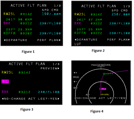
Direct-TO - Global Customer Committee News
Honeywell Goes right to the Source to Find Out What Customers Need
What is the GCC?

The Global Customer Committee, an 85-member group that includes pilots and chiefs of maintenance from corporate flight departments, as well as representatives of large aviation service centers that maintain aircraft for smaller operators, was created so that Honeywell could hear directly from customers. In addition to helping Customer & Product Support, and Business & General Aviation teams identify and address customer issues, GCC feedback provides valuable insight to all Aerospace businesses and functions.
The GCC’s mission is to prevent problems from occurring through a free flowing exchange of information between members and Honeywell. This information is consolidated into Honeywell’s “One List” and worked through a Top 25 action list that is prioritized globally.
Honeywell GCC regional representation and membership counts are: Americas – 48, Europe, Middle East, Africa and India – 26, and Asia Pacific – 11. Each region has two face to face meetings every year. In addition, there are two Global Telecoms between meetings.
How do they work?
Honeywell and the Global Customer Committee have spent 4 years refining an operating system based on a Top 25 action list, which not only balances mechanical, electrical, support and pilot issues, but also incorporates feedback from all the GCC groups around the world. Customer working teams collaborate directly with Honeywell on the highest priority actions from the Top 25 List. For more information on the operating system, please click here
Top GCC Operations (Pilot) RAIL Items
It is very important to the GCC to address pilots concerns in the Top 25 Revolving Action Item List (RAIL). Honeywell has been working very close with the Operations group to improve products and services. This partnership has produced great results, including:
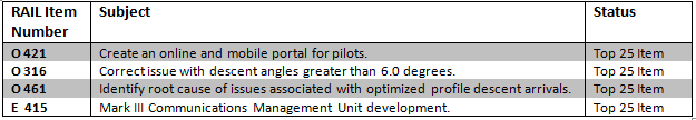
For more information, please email GCC@honeywell.com.
Interested in becoming a member or submitting an issue to the GCC? Please visit the GCC website.
Direct-TO - NavDB Update
Free Pilot Training
Honeywell offers several types of free training opportunities to customers. In addition to the free training provided during Entry into Service and operators conferences throughout the year, Honeywell provides online training available at the student’s convenience. The Honeywell Flight Technical Services webpage is the starting point to discover what’s available.
To access the Flight Technical Services webpage, go to www.mygdc.com and select the “Pilot Services” link. (No login required.)
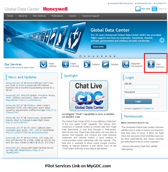
The following pages can be accessed from the webpage:
- Program pilot contact information by OEM or product
- Flight Technical Services Brochure
- Online pilot training
- Dates and locations of Honeywell Operators Conferences
- An archive of past Direct-TO FMS newsletters
- Honeywell Aero Training TV
- Go Direct Services (RNP AR and Datalink certification services)
Online Pilot Training and Honeywell Aero Training TV
The "Online Pilot Training" link is organized by OEM (i.e. Pilatus, Gulfstream, Dassault, etc.), and General categories for items of broader interest like ADS-B and WAAS/LPV. In most cases there is a PDF lesson along with a corresponding Breeze presentation.
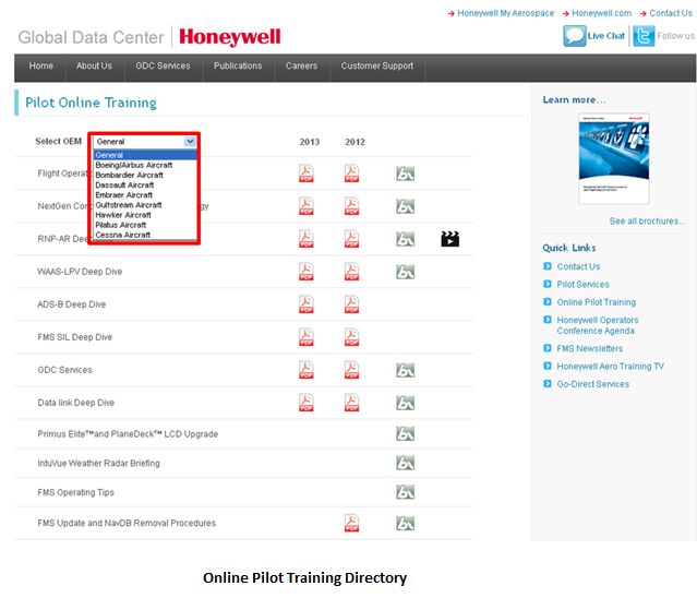
For example, selecting "Pilatus Aircraft" from the dropdown menu provides a list of available training including the PC-12NG Build 7 and Build 8 updates, along with videos covering data-loading procedures.

The latest additions to the website are the "Honeywell Aero Training TV" courses. Currently there are 12 pilot and 21 maintenance videos available. These training modules are also viewable on desktop computers and portable devices such as iPads and iPhones.

All of these resources are available for free and without signing up for access. The Flight Technical Services team is adding new content regularly.
Direct-TO - Honeywell Flight Technical Services
Operator Conference Pilot Breakout Sessions.
The Honeywell Flight Technical Services team hosts breakout sessions for pilots at approximately 15 operator conferences every year, connecting with the operators who use Honeywell products and services every day. The sessions include presentations on upcoming mandates, operational considerations pertaining to specific systems, and deep-dive discussions on new technologies. Most importantly, the pilot breakout sessions give pilots a chance to speak one-on-one with Honeywell program pilots in order to gain a better understanding of their avionics.
Honeywell operator conferences are held worldwide; from the Americas to Europe, the Middle East, Africa, and Asia. All conferences held in the USA and several abroad include a pilot breakout session. From the first breakout session of the year in Ft. Lauderdale, Florida, to the most recent in Lijiang, China, Honeywell program pilots are traveling worldwide, and have reached out to nearly 220 pilots.
This year, the breakout sessions have included discussions on worldwide ADS-B mandates, FANS 1/A and PM-CPDLC technologies, and RNP (AR) authorizations. Flight Technical Services program pilots have also spent time covering topics specific to Honeywell avionics platforms and answering individual questions posed by pilots.
The remaining operator conference schedule includes stops in Sao Paulo, Brazil on August 13th, and Dallas, Texas on September 11th. A complete schedule and registration information can be found on the Flight Technical Services Events and Training Calendar. Look for the 2014 operator conference schedule in the December issue of Direct-TO.
Pilots who can't make it to an operator conference breakout session have many opportunities throughout the year to participate in live webinars. Visit the Events and Training Calendar to view the complete schedule.
Honeywell Flight Technical Services is a group of dedicated pilots who provide customer familiarization, seminars, webinars, and "train-the-trainer" support. The team maintains currency in aircraft operations, and creates and updates training courseware and publications for Honeywell Aerospace products and services. Please visit the Flight Technical Services webpage for more information.
NOTE: Honeywell Flight Technical Services is not an FAA-certified provider of pilot training courses.
Direct-TO - GDC Update
MyGDC iPad App Version 2.0
The Honeywell Global Data Center has just released version 2.0 of the MyGDC iPad app. The app received several upgrades and new features, including:
- A redesigned trip kit manager that makes creating, e-mailing and printing a trip kit quick and easy.
- Snapshots, which allow storage of route and overlay views for offline viewing.
- A new scratchpad area to capture notes and store them for later use. Times and fuel burns can also be saved.
- WSI® Weather Integration. GDC and WSI have teamed up to bring pilots best in class aviation weather.
- Improved overlay performance to assist pilots with route decisions.
- New oceanic track overlays. Current North Atlantic (NAT) and Pacific Tracks can be overlaid on the route map.
- Integration of FAA airport diagrams, approach plates, SIDs and STARs.
- A new Help area that includes app training videos.
- Many other bug fixes and performance enhancements
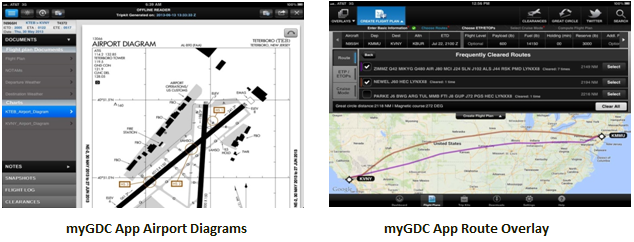
The MyGDC app is free to all Global Data Center subscribers, and can be downloaded from the Apple App Store.
With the initial release of the MyGDC app, the Global Data Center provided free premium worldwide weather products for customer evaluation. This promotion is coming to an end with the launch of MyGDC v2.0. Customers wishing to continue receiving these premium weather products should contact the GDC account management team at 888-624-3330 or 425-885-8100, option 3.
The MyGDC app will continue to receive regular upgrades and improvements. Be sure to check the Direct-TO GDC Update every month for the latest Global Data Center news.
Honeywell Global Data Center
Toll Free (US & Canada): 1-888-634-3330
International Customers: +1 425-885-8100
Fax: +1 425-885-8930
Email: gfo@mygdc.com
For important GDC updates, weather and airspace information, follow the Global Data Center on Twitter @Honeywell_GDC.
Direct-TO - Events and Training
2013 Calendar of Events and Training Opportunities
Honeywell Customer and Product Support pilots will be available at many events this year, including Honeywell Operators Conferences, online Webinars, and customer/industry events. All Honeywell events are free of charge and everyone is welcome to attend. Pilot breakout sessions and training webinars (eBroadcast sessions) are primarily for pilots, but maintenance personnel and technicians are encouraged to participate as operational tips, current issues, and new products and upgrades are covered. Instructors are Honeywell training pilots with thousands of hours of experience who are type-rated on various platforms including Gulfstream, Dassault, Bombardier, Cessna, Hawker Beech, Pilatus, and Embraer.
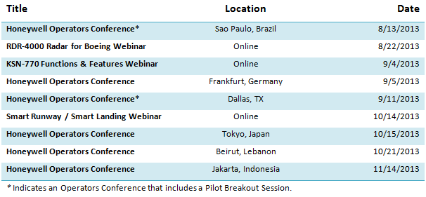
Schedule and location is subject to change based on registration for each event. Interested in attending a seminar or webinar? Most sessions require advanced registration. Contact Jeff Holt at +1-817-564-3436 or email Jeffrey.Holt@Honeywell.com.
Miss an eBroadcast session? Training is recorded and available any time by clicking here.
Direct-TO - Global Customer Committee News

The Honeywell Global Customer Committee (GCC) is pleased to announce that Pat Dunn has been elected as the GCC Chairman of Asia Pacific. Pat is currently the Chief Pilot of Asia Corporate Jet, based in Singapore.
Pat brings 36 years of experience in Business Aviation, most notably helping to build Motorola's aviation department into a global, multi-base flight operation. Pat also has vast experience with aerospace industry committees including NBAA International Operators Committee, NBAA IOC Regional Lead - Asia, IBAC Standards Board and the ICAO Asian Pacific PBN Task Force, in which he continues to be active.
Please join Honeywell in welcoming Pat as he brings his passion to improve aviation products and services to the GCC.
The Global Customer Committee (GCC) is a partnership between Honeywell and their customers. For more information on how you can join or make contributions to the GCC, visit: committees.honeywell.com.
Direct-TO - Honeywell Pilot Portal
One-Stop Shop for Pilot Resources and Training Information Coming Soon
Honeywell has produced a wealth of training materials, manuals, and other resources geared towards helping pilots operate their aircraft safely and efficiently. There are hundreds of these resources available, but finding the right one can take more time than it should. To solve this problem, Honeywell is launching a project that will consolidate all pilot-related information into a single location or "portal". Bringing everything under one roof will make finding pilot-related resources quick and easy.
This online portal will be designed specifically for pilots, by pilots. The goal is to give Honeywell customers access to everything they need through a customizable, easy to use interface. To accomplish this, Honeywell has engaged the Global Customer Committee to provide pilot input, testing, and validation throughout the development process.
Development is just getting started, but pilots can register for the Honeywell Pilot Mailing List to make sure they're ready to enjoy the portal's benefits as soon as it's released. Pilots who would like to participate in the design and testing process can indicate their interest in the comments field on the registration form.
This project is one of many great ideas under development by the Global Customer Committee. For more information on joining or making contributions to the GCC, visit http://committees.honeywell.com.
Direct-TO - Honeywell Go-Direct
F900 EASy II RNP AR Operational Approval
The Honeywell Flight Department has received operational approval for RNP AR approaches with its Falcon 900 EASy II aircraft. The operational approval applies to all US public RNP AR approaches.
The EASy II upgrade received FAA certification in 2011. Prior to granting operational approvals, specific review of the aircraft qualification for RNP AR was required by the FAA Flight Standards and Airworthiness groups. This process was completed during Honeywell's application.
F900/EASy II RNP AR Capability
The F900 EASy II is approved for RNP AR approaches to lines of minima for RNP 0.3, and the use of Radius-to-Fix (RF) legs. Missed approaches with RNP values below 1.0 are also approved. RNP AR approaches are charted as RNAV (RNP) RWY (XX).
Note: An FAA LOA/Ops Spec is required prior to conducting RNP AR approaches. RNP AR approaches are only included in navigation databases of approved operators.
How to Get Operational Approval for RNP AR
All operators, Part 91 and 135, must acquire operational approval via LOA or Ops Spec respectively. Guidance for operational approval is contained in FAA Advisory Circular 90-101A (Canadian-registered operators see AC 700-024, European-registered operators see AMC 20-26).
Honeywell offers support to anyone looking to save time and simplify the approval process. Their Go-Direct consultancy service helps operators complete the application along with the required operational procedures and documentation. Additionally, Honeywell offers navigation database services which meet the requirements for database validation in the RNP AR guidance.
Requests for more information about Honeywell's RNP consultancy services can be made through RNP@honeywell.com.
Direct-TO - Industry Update
ATN Network (PM-CPDLC) â€" Europe's Data Link Mandate
Link 2000+ is a European program that mandates Controller Pilot Data Link Communications (CPDLC) capabilities within Western Europe. The program supplements voice communications between pilots and air traffic controllers and is expected to reduce frequency congestion and improve safety.
The Link 2000+ program does not utilize the traditional Future Air Navigation System (FANS) network, which relies on both satellite and ground-based VHF data link sub-systems. Instead, it is based on the implementation of the Aeronautical Telecommunications Network (ATN) that utilizes only ground-based VHF data link (VDL Mode 2) stations.
CPDLC that utilizes the ATN network is referred to as Protected Mode Controller Pilot Data Link Communication (PM-CPDLC). PM-CPDLC offers higher speed data link capabilities and logic that reduces mis-delivery of messages. PM-CPDLC is currently being used over Western Europe with Communication Management Units (CMUs) running the ATN protocol and communicating via higher speed VDL Mode 2 transceivers.
In-service aircraft with individual airworthiness certificates dated prior to January 1, 2014 and equipped with FANS qualify for exemption for the lifetime of the aircraft. This is a major incentive for business aircraft operators to equip with FANS 1/A today, in addition to enjoying the operational capabilities of using ADS-C and CPDLC. Unless otherwise exempt, aircraft entering into service after February 7, 2015 are required to comply with the mandate which requires aircraft to be equipped with PM-CPDLC capabilities.
Automatic and temporary exemptions are available for aircraft that qualify under Article 3 or Article 14 of EC Reg. No. 29/2009. Click here to view the complete articles. It is recommended that operators contact the appropriate Original Equipment Manufacturer (OEM) for additional exemption information.
Direct-TO - Global Data Center Update
MyGDC.com GDC Tips and Tricks
The Global Data Center's website, www.MyGDC.com, makes it easy to choose the best route based on performance, weather, and ATC programs. The Create Flight Plan menu offers several routing options to best meet crew needs.
Quick Flight Plan
When in a hurry, the new Quick Flight Plan feature allows pilots to generate a flight plan using an optimized routing, cruise mode, and altitude. Only the information required under the Basic Information tab (fields marked by a red asterisk) is required. A recall number is generated immediately by clicking on the blue "Complete Quick Flight Plan" button. The flight plan can be filed with ATC by entering a few more details on the filing page that follows.
Frequently/Recently Cleared Routes
The Frequently/Recently Cleared Routes list presents routes for flights between popular city pairs. These routes are especially useful when flying through congested airspace, such as the northeastern United States. The most frequently cleared routes can be found at the top of the list.
This option is particularly useful when planning around weather. Most Frequently/Recently cleared routes are also a great indicator of updated arrival and departure procedures.
Placing the mouse cursor over each route will indicate the total number of times it has been cleared, the number of times it has been cleared in the last 30 days, and the last time it was cleared. Aircraft type data is also displayed, which helps pilots to avoid filing the wrong SID or STAR.
EUROCONTROL and Other Routes
Selecting the EUROCONTROL Routes option is recommended to avoid an extensive reroute when filing through EUROCONTROL airspace. Using real-time data, the GDC's EUROCONTROL routes present ATC preferred routing.
The Other Routes section includes ATC and GDC-preferred routes, Oceanic Tracks, and Coded Departure Routes (CDRs). Toggling the radio buttons populates the selected routes.
Winds & Temperature Optimized Routes
Selecting this option tells the flight planning system to generate a route based on up-to-date forecasts for wind and temperature aloft. This option is not recommended on busier routes as it may result in extensive reroutes. Instead, this is better suited for longer flights, city pairs with light traffic, and when other routing options are unavailable. These routes can save GDC customers significant time and fuel.
User Defined Routes
To enter a specific route that is not available under the other route options, check the box for User Defined Routes. The route should be entered without SIDs and STARs in the box marked Waypoints. Arrival and departure procedures are selected separately. Click on the "SID" and "STAR" buttons on either side of the waypoint box. FAA charts for these procedures can be viewed by clicking on the PDF icon on the right side of each list. Viewing the procedure helps pilots ensure that they are selecting the correct procedure for their aircraft and route.
Ask the GDC
Pilots and dispatchers who have further questions about the GDC website, don't have access to a computer, or simply prefer talking to someone, can call the GDC directly for help. Expert assistance from the GDC's experienced and knowledgeable Flight Data Specialists is available 24 hours a day, seven days a week. 24-hour assistance is also available through the GDC's new Live Chat feature at MyGDC.com.
| Honeywell Global Data Center |
| Toll Free (US & Canada): 1-888-634-3330 |
| International Customers: +1 425 885-8100 |
| Fax: +1 425-885-8930 |
| Email: gfo@mygdc.com |
| www.MyGDC.com |
For the latest news and updates as well as important weather and airspace information, follow the Global Data Center on Twitter @Honeywell_GDC
Direct-TO - Pilatus PC-12 NG Update
Four New Apps Put Key Information at Pilots' Fingertips
Honeywell has launched four new iPad applications to simplify and modernize the flight experience for Pilatus PC-12 NG pilots and owners. Through close collaboration with Pilatus, Jeppesen, and Aspen Avionics, Honeywell customized four applications with interfaces that cater specifically to pilots' needs and preferences. These apps increase usability and convenience by bringing key flight deck tools to personal devices. When used in conjunction with connectivity hardware from Aspen, the apps provide even more functionality for pilots, operators and passengers alike.
Four Applications for the PC-12 NG
INDS Data Manager App: Developed in coordination with Jeppesen, this app accelerates and modernizes the process of obtaining and loading updated charts and maps, as well as navigation data. As mandated by the Federal Aviation Administration, these databases must be refreshed every 14 to 28 days. With the new INDS app and the updated hardware, PC-12 NG owners and operators will enjoy wireless access and short upload times.
MyGDC App: An enhancement to the Honeywell Global Data Center (GDC) application, the MyGDC app for iPad brings the power and convenience of GDC services to customers on the move. In addition, operators of the Pilatus PC-12NG will soon be able to wirelessly upload their flight plans from the MyGDC app into the Honeywell Apex integrated flight deck. The first version of this app is available to download from the Apple app store today, with further updates coming soon.
mySupport Maintenance Download App: Enables Pilatus operators and maintenance department personnel to wirelessly download and email the aircraft condition monitoring data and fault history databases to targeted recipients. Wireless downloading combined with file transfer provides added convenience over previous hard-wired connections and enables collaborative maintenance actions, speeding the provisioning and repair processes.
Pilatus FlightPath App: Bring real-time flight monitoring to business aviation passengers. Working with the Aspen CG100P, the app showcases multiple aircraft parameters allowing light business aircraft passengers to monitor their flight's progress on worldwide terrain maps in real time.
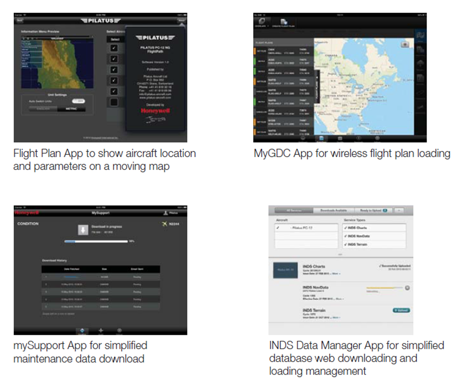
The new and updated apps are available for download from the Apple App Store.
Direct-TO - Events and Training
2013 Calendar of Events and Training Opportunities
Honeywell Customer and Product Support pilots will be available at many events this year, including Honeywell Operators Conferences, online Webinars, and customer/industry events. All Honeywell events are free of charge and everyone is welcome to attend. Pilot breakout sessions and training webinars (eBroadcast sessions) are primarily for pilots, but maintenance personnel and technicians are encouraged to participate as operational tips, current issues, and new products and upgrades are covered. Instructors are Honeywell training pilots with thousands of hours of experience who are type-rated on various platforms including Gulfstream, Dassault, Bombardier, Cessna, Hawker Beech, Pilatus, and Embraer.
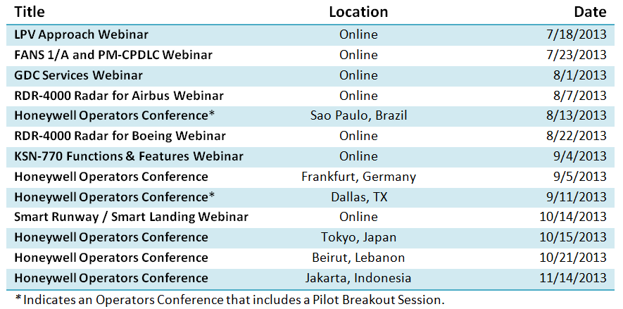
Schedule and location is subject to change based on registration for each event. Interested in attending a seminar or webinar? Most sessions require advanced registration. Contact Jeff Holt at +1-817-564-3436 or email Jeffrey.Holt@Honeywell.com.
Miss an eBroadcast session? Training is recorded and available any time by clicking here.
Direct-TO - NavDB Update
Approaches with Flight Path Angles in Excess of 6.0 Degrees Returning to Navigation Database
In the December 2012 edition of Direct-TO, the NavDB Update addressed the removal of procedures that contained a Flight Path Angle (FPA) that exceeded 6.0 degrees. After careful consideration, a change is being made to the Honeywell database compiling software, allowing all procedures that exceed 6.0 degrees to be included in the navigation database by including intermediate step-down fixes. The approach procedures that exceed 6.0 degree FPA are listed here and should be included in all business and corporate navigation databases later this year.
There were several factors that contributed to the removal of these procedures; primarily, the FMS's limitation to calculate a maximum of 6.0 degrees. This led to a shallower than expected descent path on steep approach procedures because intermediate step-down fixes are excluded and the vertical path defined by the procedure would be restricted to 6.0 degrees. This would create a vertical path that, if followed, could violate terrain separation guaranteed by procedure design. In the below example, the VOR DME â€" C at Aspen, Colorado (KASE), the path derived by procedure design is 9.61 degrees. Without the intermediate step-down fix included the FMS calculated path from the missed approach point backward would violate the MDA for the segment between ALLIX and ZIGBU.
The inclusion of intermediate step-down fixes does not solve the FMS limitation of a maximum calculated angle of 6.0 degrees; however, it does provide a waypoint and altitude from which the FMS calculated path that will not violate protected airspace. As displayed in the FMS image below, the maximum angle of 6.0 degrees is displayed from the missed approach point (MAFMU) to the intermediate step-down fix (ZIGBU). The preceding waypoints are calculated by the FMS and are also listed; because, they are less than 6.0 degrees and the FMS calculated vertical angle will be shown.
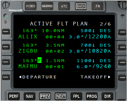
The FAA has made it policy to publish Vertical Descent Angles (VDA) on non-precision approaches. This VDA is computed from the runway Threshold Crossing Height (TCH) to the Final Approach Fix (FAF) or Intermediate step-down fix. Per the Aeronautical Information Manual (AIM) 5.4.4 (i) the "VDA provides the crew with information about the descent rate required to land straight in from the FAF or step down fix to the threshold." The AIM further states that this angle is not intended to imply that straight in landings are recommended or even possible â€" as the descent rate can exceed aircraft capabilities. It is important to note that the altitude at a missed approach point is not the MDA listed on the charted procedure. This encoded altitude in the navigation database is the point in space where the vertical path from the TCH to the FAF or intermediate step-down fix crosses at the missed approach point. The VDA is provided primarily to aid in situational awareness and is advisory in nature.
If you have questions or would like more information, please email talkfms@honeywell.com
.Direct-TO - NavDB Update
Optimized Profile Descents
As part of the NEXTGEN Trajectory-Based Operations initiative, the FAA has begun developing Standard Terminal Arrival Route (STAR) procedures that focus on a continuous descent concept. This modeling will allow for reduced fuel consumption and emissions as the aircraft will make the entire descent at, or near flight idle. These are referred to as Optimized Profile Descent (OPD) procedures. In 2009, the FAA began testing OPD procedures into the Anchorage, Alaska airport (PANC) with traffic originating from the contiguous United States. The study revealed notable fuel savings and reduced communication, as a single clearance of "descend via" was issued. This allowed crews to determine the most suitable top of descent point to permit an idle descent. When flying this type of arrival, crews should expect a "descend via" clearance and must navigate vertically and laterally to meet all published restrictions.
The "descend via" clearance transfers the vertical path profile from the air traffic controller to the pilot, reducing communication and allowing flight crews to manage the vertical profile per the procedure. The charted altitude constraints must be honored. However, most are window constraints that allow for some vertical variation. This concept allows heavier aircraft to begin a descent earlier than lighter ones.
The Flight Management System (FMS) is typically used to calculate the vertical path, which is optimized by performance calculations. If the FMS is not able to calculate the vertical path, the pilot is still responsible for meeting the altitude constraints. Additionally, heavy reliance on the FMS to calculate the vertical path has led pilots to lose vertical situational awareness in the event of an FMS failure or loss of vertical data. Therefore, pilots should spend time briefing the procedure prior to flying it, and be fully aware of the altitude constraints and how to navigate them in the event the FMS is unable to provide suitable vertical navigation. Depending on the aircraft being flown and the software version installed, vertical navigation (VNAV) may or may not be available.
An example of an OPD, the EAGUL FIVE Arrival into the Phoenix Sky Harbor Airport (KPHX), is shown below. Note the numerous altitude and speed constraints with which flight crews must comply.
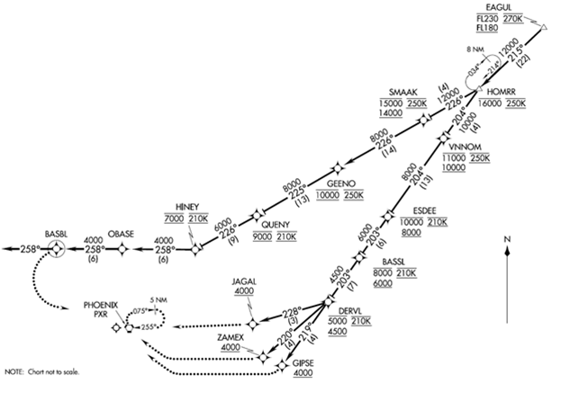
Procedure designers attempt to optimize descents using a constant glide path; however, the path may not be a consistent angle. The profile view of the KPHX EAGUL FIVE Arrival to runway 26 is shown below. The exact altitudes that this path will cross are depicted by the blue line, based on a constant 3-degree glide path. Note that the window constraint at VNNOM is violated if this path is maintained. An earlier or steeper descent is required to meet the 11,000 foot ceiling at VNNOM. FMS's that have VNAV functionality are designed to take this into consideration; the FMS will use the default setting of 3.0 degrees and place the Top of Descent (TOD) accordingly to meet the constraint defined in the navigation database. The pilot should expect the descent to become more shallow until reaching ESDEE, where the aircraft could then rejoin the 3.0 degree path - ultimately until touchdown.
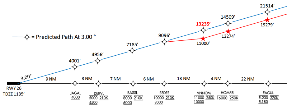
In the event the FMS does not compute a VNAV path, use the rule of thumb that one-half of the ground speed multiplied by 10 will yield an approximate vertical speed. For example, when crossing EAGUL at 270KIAS, the true airspeed would be around 400kts. Therefore, the initial vertical speed to maintain a 3.0 degree path would be around 2000 feet per minute. Using ground speed allows crews to compensate for headwinds or tailwinds and have a more accurate vertical path.
With increased fuel efficiency, reduced communications and reduced emissions, the FAA will be implementing more and more of these OPD STAR procedures. In an effort to help improve how the Honeywell FMS flies these procedures, pilots are requested to submit any reports of VNAV issues. This will allow Honeywell engineers to analyze the specific procedures and scenarios that are causing problems, and develop stronger software coding to address the numerous OPD vertical and speed constraints. Please submit all comments via email to talkfms@honeywell.com, and please write OPD STAR in the subject line.
Direct-TO - GDC Update
Global Data Center Collaborates with Jetex to Provide Worldwide Flight Support
Honeywell and Jetex Flight Support have joined forces to offer comprehensive flight support services worldwide. Unveiled at EBACE 2013, this agreement will allow both companies to expand their offerings and serve their customers in new ways. Global Data Center (GDC) subscribers will now be able to utilize Flight Sentinel services combined with Jetex's expertise in international handling.
The agreement will create a one-stop shop for international flight planning and expand the coverage of Flight Sentinel services to customers operating worldwide. Pilots and dispatchers will have access to international trip information under one interface on the MyGDC website.
Flight Sentinel is a concierge-style flight planning, following, and delay mitigation service offered to GDC customers. The Flight Sentinel team uses their extensive knowledge, proprietary software tools, and participation in the FAA's Collaborate Decision Making (CDM) program to help pilots avoid delays and receive important information pre-departure and enroute.
Jetex offers premium ground handling and concierge services worldwide from their offices in Europe, the Middle East, and East Asia. Ground handling offerings include ground transportation, catering, security, visas, and other related services.
Jetex and Honeywell currently plan on offering the service beginning in the fourth quarter of this year. More details will be announced in the near future. Look for further updates on the GDC website or contact the GDC for more information.
Honeywell Global Data Center
Toll Free (US & Canada): 1-888-634-3330
International Customers: +1 425 885-8100
Fax: +1 425-885-8930
Email: gfo@mygdc.com
www.MyGDC.com
For the latest news and updates as well as important weather and airspace information, follow the Global Data Center on Twitter @Honeywell_GDC.
Direct-TO - Events and Training
2013 Calendar of Events and Training Opportunities
Honeywell Customer and Product Support pilots will be available at many events next year, including Honeywell Operators Conferences, online Webinars, and customer/industry events. All Honeywell events are free of charge and everyone is welcome to attend. Pilot breakout sessions and training webinars (eBroadcast sessions) are primarily for pilots, but maintenance personnel and technicians are encouraged to participate as operational tips, current issues and new products and upgrades are covered.
Instructors are Honeywell training pilots with thousands of hours of experience who are type-rated on various platforms including Gulfstream, Dassault, Bombardier, Cessna, Hawker Beech, Pilatus and Embraer.
| Title | Location | Date |
|---|---|---|
| Honeywell Operators Conference | Singapore | 6/18/2013 |
| Honeywell Operators Conference* | Toluca, Mexico | 6/25/2013 |
| Honeywell Operators Conference* | Johannesburg, S. Africa | 7/4/2013 |
| Honeywell Operators Conference* | Lijiang, China | 7/16/2013 |
| LPV Approach Webinar | Online | 7/18/2013 |
| FANS 1/A and PM-CPDLC Webinar | Online | 7/23/2013 |
| GDC Services Webinar | Online | 8/1/2013 |
| Honeywell Operators Conference* | Sao Paulo, Brazil | 8/13/2013 |
| KSN-770 Functions & Features Webinar | Online | 9/4/2013 |
| Honeywell Operators Conference | Frankfurt, Germany | 9/5/2013 |
| Honeywell Operators Conference* | Dallas, TX | 9/11/2013 |
| Honeywell Operators Conference | Moscow, Russia | 9/16/2013 |
| Smart Runway / Smart Landing Webinar | Online | 10/14/2013 |
| Honeywell Operators Conference | Tokyo, Japan | 10/15/2013 |
| Honeywell Operators Conference | Beirut, Lebanon | 10/21/2013 |
| Honeywell Operators Conference | Jakarta, Indonesia | 11/14/2013 |
* Indicates an Operators Conference that includes a Pilot Breakout Session.
Interested in attending a seminar or webinar? Most sessions require advanced registration. Contact Jeff Holt at +1-817-564-3436 or email Jeffrey.holt@honeywell.com.
Schedule and location is subject to change based on registration for each event.
Miss an eBroadcast session? Training is recorded and available any time by clicking here
https://www.mygdc.com/new/static/cpsfltops-training.php.
Direct-TO - Pilot Support and Online Training
Pilot Support and Online Training
Online pilot and technical training on various Honeywell products and services can be accessed through the link below. https://www.mygdc.com/new/static/pilot-services.php
Select from the list of available sessions. Each session is from 45 minutes to 1 hour in duration. Current online training modules include:
- IntuVue Weather Radar
- Dassault EASy II
- Gulfstream PlaneViewTM Cert Foxtrot and Cert Golf
- Bombardier Batch 3
- Primus EliteTM and PlaneDeckTM LCD Display Upgrade
- Airspace Mandates and Updates (RNP AR, CPDLC, SBAS, ADS)
- FMS Operating Tips
- Downloading INDS Databases
- PC-12 Laptop Configuration
- PC-12 Laptop Downloading
- PC-12 SD Dataloading
- Using INDS JSUM
- Pegasus Step 1A
- Pilatus PC-12 NG Build 7
Direct-TO - Pilot Support Information
Pilot Support Contact Information:
Honeywell's Customer & Product Support organization employs a group of experienced pilots dedicated to supporting fielded aircraft and providing training for the avionics installed during production or retrofit. Pilots are aircraft manufacturer-focused and can be contacted via email or phone for operational-type questions. For information and links to pilot training, operator conference agendas and locations, as well as pilot services go to https://www.mygdc.com/new/static/pilot-services.php
 |
Jeff Holt, Manager Pilot Training Type ratings - LR-JET, F2000 EX, F7X, EMB145 & B737 Jeff supports Dassault and Embraer Email: jeff.holt2@honeywell.com Phone: (817) 564-3436 |
 |
Steve Hammack, Technical Pilot Certifications - PC-12 NG Steve supports Pilatus, Viking & HAIG Email: stephen.hammack@honeywell.com |
 |
Roger Moore, Technical Pilot Type ratings - LR-JET, A320, A330, B777 & DC-9/MD-80 Roger supports Airbus & Boeing Email: roger.moore@honeywell.com Phone: (602) 436-1528 |
 |
David Rogers, Technical Pilot Type ratings - CE750, CE680, CE560, G-V David supports Gulfstream, Cessna & Honeywell FMS (NZ & Epic) Email: david.rogers@honeywell.com Phone: (425) 516-8654 |
 |
Barrie Elliott, Training Specialist Certifications - PC-12 NG Barrie supports Bendix King and Skyforce Email: barrie.elliott@honeywell.com Phone: +44 797-009-2004 |
 |
Brock Graham, Technical Pilot Type ratings: EMB-145, ERJ-170, ERJ-190 Supports: Embraer and Hawker Email: brock.graham@honeywell.com Phone: (602) 436-2471 |
 |
Brandon Burton, Training Specialist Type ratings - F900 Brandon supports datalink and surveillance Email: brandon.burton@honeywell.com Phone: (425) 615-5963 |
 |
Jim Johnson, Sr. Training Specialist Jim supports RNP and Go-Direct Consultancy Services Email: james.johnson2@honeywell.com Phone: (817) 504-3888 |
 |
Chris Van Cise, Training Specialist Certifications - PC-12 NG Chris supports datalink and the Global Data Center Email: christopher.vancise@honeywell.com Phone: (425) 281-2051 |
For field support, or to find your local Honeywell representative, consult the Business & General Aviation Customer Support and Aftermarket Sales Directory. http://www51.honeywell.com/aero/common/documents/BGA-Customer-Support-Aftermarket-Sales-Directory.pdf
